
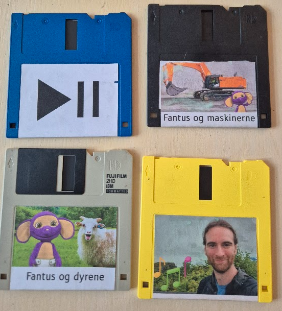
Floppy Disks: the best TV remote for kids
Modern TVs are very poorly suited for kids. They require using complicated remotes or mobile phones, and navigating apps that continually try to lure you into watching something else than you intended to. The usual scenario ends up with the kid feeling disempowered and asking an adult to put something on. That something ends up on auto-play because then the adult is free to do other things and the kid ends up stranded powerless and comatose in front of the TV.
Instead I wanted to build something for my 3-year old son that he could understand and use independently. It should empower him to make his own choices. It should be physical and tangible, i.e. it should be something he could touch and feel. It should also have some illusion that the actual media content was stored physically and not un-understandably in “the cloud”, meaning it should e.g. be destroyable — if you break the media there should be consequences. And there should be no auto-play: interact once and get one video.
Floppy disks are awesome!
And then I remembered the sound of a floppy disk. The mechanical click as you insert it, the whirr of the disk spinning, and the sound of the read-head moving. Floppy disks are the best storage media ever invented! Why else would the “save-icon” still be a floppy disk? Who hasn’t turned in a paper on a broken floppy disk, with the excuse ready that the floppy must have broken when the teacher asks a few days later? But kids these days have never used nor even seen a floppy disk, and I believe they deserve this experience!
Building on the experience from the Big Red Fantus-Button, I already had a framework for controlling a Chromecast, and because of the netcat | bash shenanigans it was easily extendable.
My first idea for datastorage was to use the shell of a floppy disk and floppy drive, and put in an RFID tag; this has been done a couple of times on the internet, such as RFIDisk or this RaspberryPi based RFID reader or this video covering how to embed an RFID tag in a floppy disk. But getting the floppy disk apart to put in an RFID tag and getting it back together was kinda wonky.
When working on the project in Hal9k someone remarked: “Datastorage? The floppy disk can store data!”, and a quick prototype later this worked really, really, well. Formatting the disk and storing a single small file, “autoexec.sh”, means that all the data ends up in track 0 and is read more or less immediately. It also has the benefit that everything can be checked and edited with a USB floppy disk drive; and the major benefit that all the sounds are completely authentic: click, whirrr, brrr brrr.
Autorun for floppy disks is not really a thing.
The next problem to tackle was how to detect that a disk is inserted. The concept of AutoRun from Windows 95 was a beauty: insert a CD-ROM and it would automatically start whatever was on the media. Great for convenience, quite questionably for security. While in theory floppy disks are supported for AutoRun, it turns out that floppy drives basically don’t know if a disk is inserted until the operating system tries to access it! There is a pin 34 “Disk Change” that is supposed to give this information, but this is basically a lie. None of the drives in my possession had that pin connected to anything, and the internet mostly concurs. In the end I slightly modified the drive and added a simple rolling switch, that would engage when a disk was inserted.
A floppy disk walks into a drive; the microcontroller says “hello!”
The next challenge was to read the data on a microcontroller. Helpfully, there is the Arduino FDC Floppy library by dhansel, which I must say is most excellent. Overall, this meant that the part of the project that involved reading a file from the floppy disk FAT filesystem was basically the easiest part of all!
However, the Arduino FDC Floppy library is only compatible with the AVR-based Arduinos, not the ESP-based ones, because it needs to control the timing very precisely and therefore uses a healthy amount of inline assembler. This meant that I would need one AVR-based Arduino to control the floppy disk, but another ESP-based one to do the WiFi communication. Such combined boards do exist, and I ended up using such a board, but I’m not sure I would recommend it: the usage is really finagly, as you need to set the jumpers differently for programming the ATmega, or programming the ESP, or connecting the two boards serial ports together.
A remote should be battery-powered
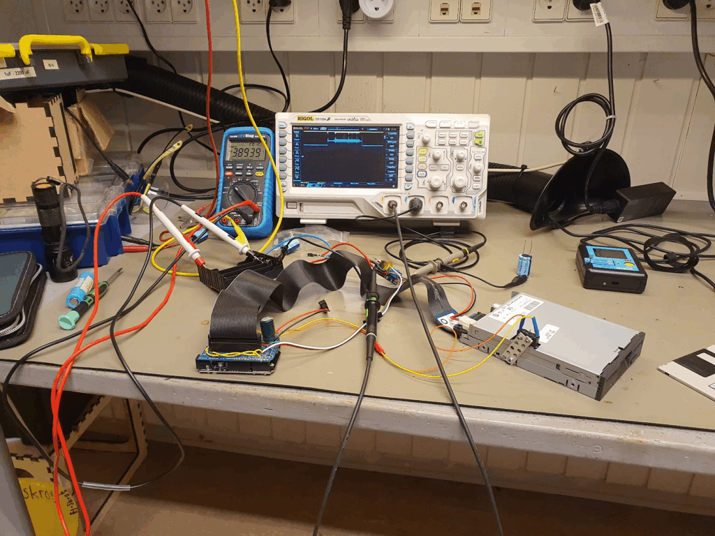
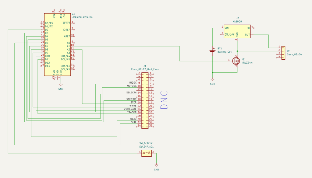
A remote control should be portable, and this means battery-powered. Driving a floppy disk of of lithium batteries was interesting. There is a large spike in current draw when the disk needs to spin up of several amperes, while the power draw afterwards is more modest, a couple of hundred milliamperes. I wanted the batteries to be 18650s, because I have those in abundance. This meant a battery voltage of 3.7V nominally, up to 4.2V for a fully charged battery; 5V is needed to spin the floppy around, so a boost DC-DC converter was needed. I used an off the shelf XL6009 step-up converter board. At this point a lot of head-scratching occurred: that initial spin-up power draw would cause the microcontroller to reset. In the end a 1000uF capacitor at the microcontroller side seemed to help but not eliminate the problem.
One crucial finding was that the ground side of the interface cable should absolutely not be connected to any grounds on the microcontroller side. I was using a relatively simple logic-level MOSFET, the IRLZ34N, to turn off the drive by disconnecting the ground side. If any ground is connected, the disk won’t turn off. But also: if any logic pin was being pulled to ground by the ATmega, that would also provide a path to ground. But since the ATmega cannot sink that much current this would lead to spurious resets! Obvious after the fact, but this took quite some headscratching. Setting all the logic pins to input, and thus high impedance, finally fixed the stability issues.
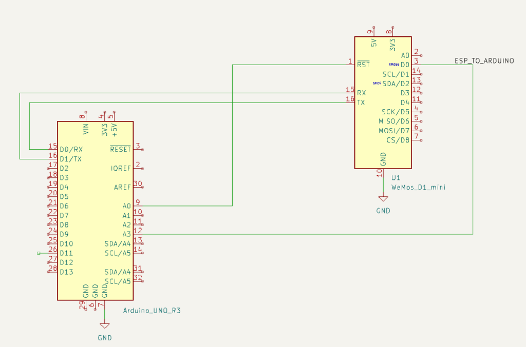
After fixing the stability, the next challenge was how to make both of the microcontrollers sleep. Because the ATmega sleep modes are quite a lot easier to deal with, and because the initial trigger would be the floppy inserting, I decided to make the ATmega in charge overall. Then the ESP has a very simple function: when awoken, read serial in, when a newline is found then send off that complete line via WiFi, and after 30 seconds signal to the ATmega that we’re sleeping, and go back to sleep.
The overall flow for the ATmega is then:
- A disk is inserted, this triggers a interrupt on the ATmega that wakes up.
- The ATmega resets the ESP, waking it from deep sleep.
- The ATmega sends a “diskin” message over serial to the ESP; the ESP transmits this over WiFi when available.
- The ATmega turns on the drive itself, and reads the disk contents, and just sends it over serial to the ESP.
- Spin down the disk, go to sleep.
- When the disk is ejected, send a “diskout” message over serial, resetting the ESP if needed.
- Go back to 1.
The box itself is just lasercut from MDF-board. For full details see the FloppyDiskCast Git repository.
Server-side handlers
Responding to those commands is still the netcat | bash from the Big Red Fantus-Button, which was simply extended with a few more commands and capabilities.
diskin always sends a “play” command to the Chromecast.diskout always sends a “pause” command to the Chromecast.
Other commands like dad-music are handled in one of two ways:
- Play a random video from a set, if a video from that set is not already playing: e.g.
dad-musicwill randomly play one of dad’s music tracks – gotta influence the youth! - Play the next video from a list, if a video from the list is not already playing: e.g.
fantus-maskinernewill play the next episode, and only the next episode.
Common for both is that they should be idempotent actions, and the diskin shortcut will make the media resume without having to wait for the disk contents itself to be read and processed. This means that the “play/pause” disk just contains an empty file to work.
Questionable idea meets real-world 3 year old user
The little guy quickly caught on to the idea! Much fun was had just pausing and resuming music and his Fantus TV shows. He explored and prodded, and some disks were harmed in the process. One problem that I did solve was that the read head stayed on track 0 after having read everything: this means that when the remote with disk inside it is tumbled around, the disk gets damaged at track 0. To compensate for this, I move the head to track 20 after reading has finished: any damage is then done there, where we don’t store any data. As a bonus it also plays a little more mechanic melody.
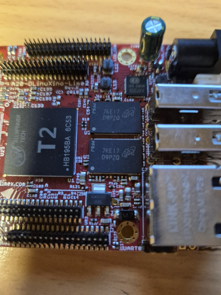
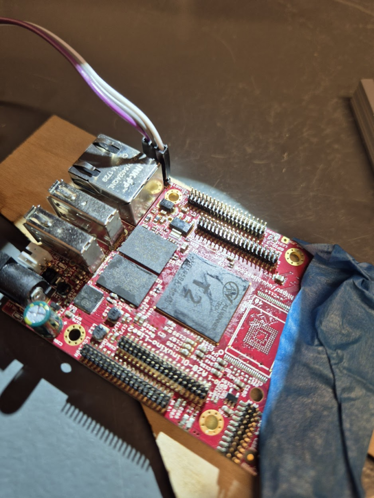
Upgrading the Olimex A20 LIME2 to 2GB RAM, by learning to BGA solder and deep diving into the U-Boot bootloader process
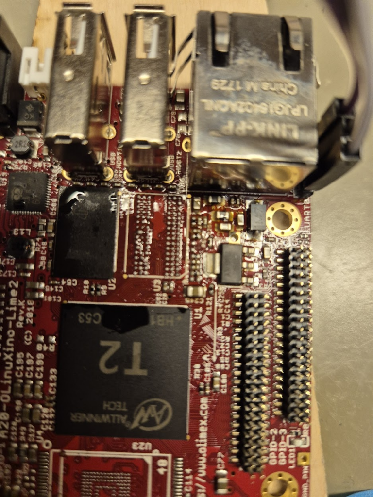
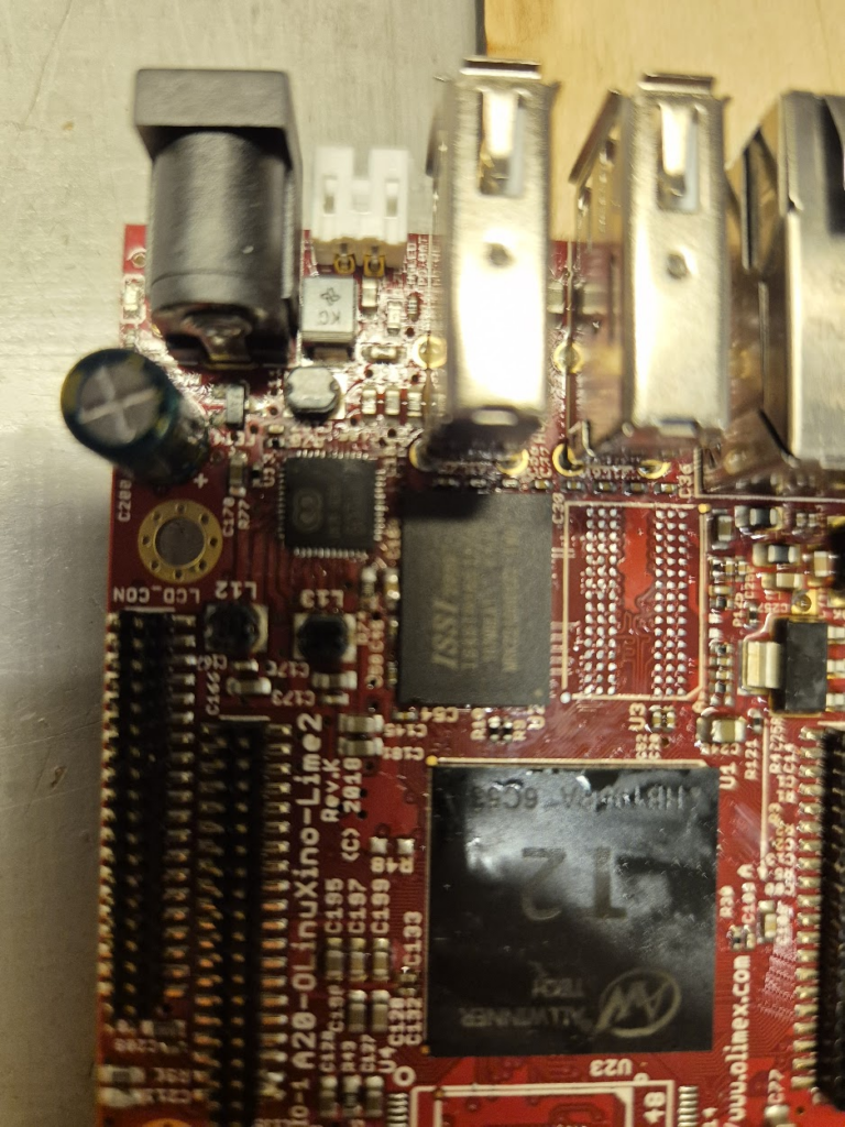
As I’ve written about previously I have had the Olimex A20-OLinuXino-LIME2 in service for quite some time. But one thing that I’ve been curious about is why it’s only available with 1GB of RAM, when the A20 chip itself can support up to 2GB? Could it be upgraded to 2GB RAM by a simple swap in of a larger memory module?
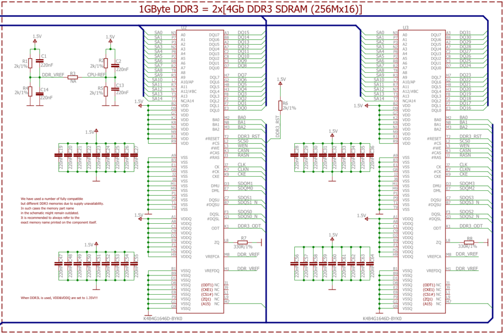
If you check the schematic the address lines are actually wired up: both A14 and A15 which are labelled NC (no-connect) on the chips are wired up on the address bus, meaning a full 2¹⁶ row addresses should be addressable. So this might actually work out!
Detour: How do CPUs access memory?
From a very high level the way a CPU accesses memory is the same all the way from a small microprocessor like the RP2040 up to a x86. There are a number of pins connecting the CPU and the RAM:
- A number of address lines, e.g. A0–A15 in our case. These are always driven by the CPU.
- A number of data lines, e.g. DQ0–DQ15. These are bi-directional and driven by the CPU for writes, but by the RAM for reads.
- A couple of signalling lines to control the communication, e.g. the shared clock, or the CPU signaling that the address lines are set with the address for a read, or the RAM signaling that the data lines are populated with the data read out. These can be quite complicated, as seen with DDR3 in this instance, where signalling talks about “banks”, “lower/upper byte data strobe”, “data masks” and “chip select”.
The most crude form of using more than one RAM chip would be to use “chip select” as known from SPI or I2C communication. This is however not how it’s done on the LIME2: address, data and chip select lines are wired in parallel for the two chips. The only difference in wiring is on the “DMU”, “DML”, and “DQSU” and “DQSL” lines: these are used for lower and upper byte data strobes, meaning that the same address is setup for both chips, and then the chips are strobed one at a time – effectively allowing each chip to prepare the read in parallel.
Finding compatible chips with 256Mx16
Luckily DDR chips are standardized, but it seems that the standardisation does not quite go all the way to the datasheets, in e.g. pin naming and concepts. But at least the density and organization are standardised: the 256M is the number of different addressable storage locations, and the x16 is how many bits are stored per location. Multiplying those gives the number of megabits stored, 4096 megabits in this case, so dividing by 8 gives the number of megabytes stored: 512MiB.
Looking at the pinout for the specified chip (K4B4G1646D-BYK0, a Samsung chip):
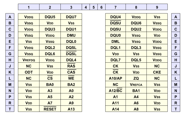
We can see it specifies only address lines A0–A14, which is enough for a 256M module. But the LIME2 schematic was helpful enough to hookup A15 to the JEDEC standard location, even if that pin is NC on all memory modules shipped. This might actually work!
The last crucial parameter for selecting bigger RAM chips is the supply voltage. DDR3 comes in both standard and low-voltage (DDR3L) variants. The LIME2 schematic actually just specifies that “When DDR3L is used, VDD&VDDQ are set to 1.35V!!!“, so to know which it is we would have to look at the particular board and measure the power supply line. But luckily, almost all DDR3L chips are backwards compatible to the 1.5V DDR3 level, so as long as we can find a DDR3L chip voltage shouldn’t be an issue.
So in theory any 512Mx16 DDR3L chip should work. In practice I ended up trying two variants:
- Micron MT41K512M16, which seems to be the only option on AliExpress, and cheap, but which (spoiler alert!) I did not get working
- ISSI IS46TR16512BL, which I did get working, but is more expensive to the point that the two needed RAM chips cost more than the LIME2 itself.
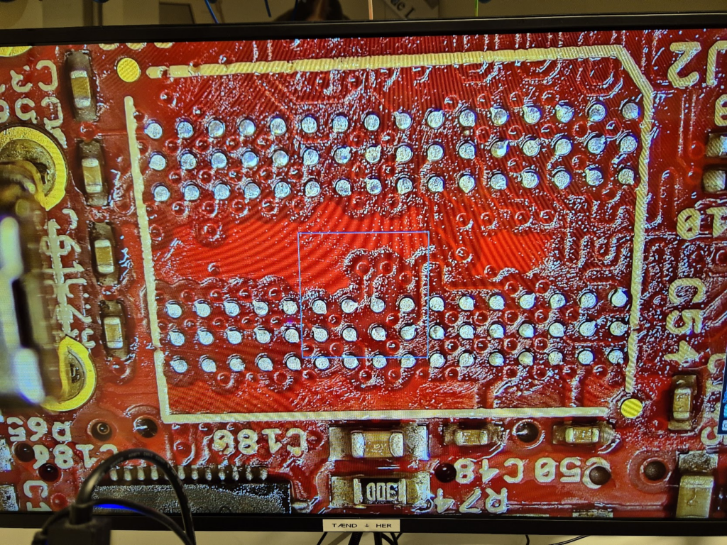
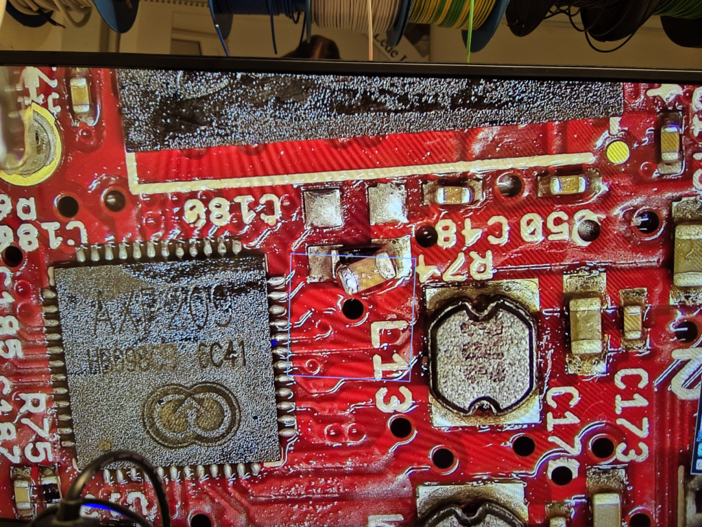
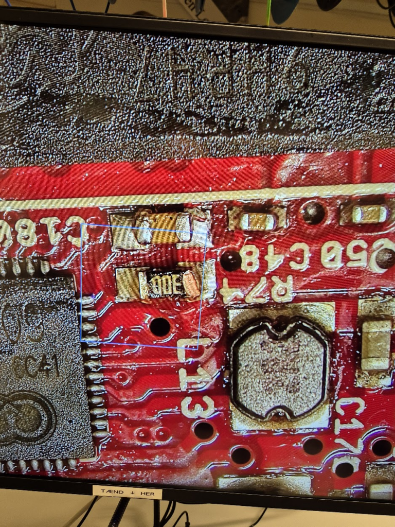
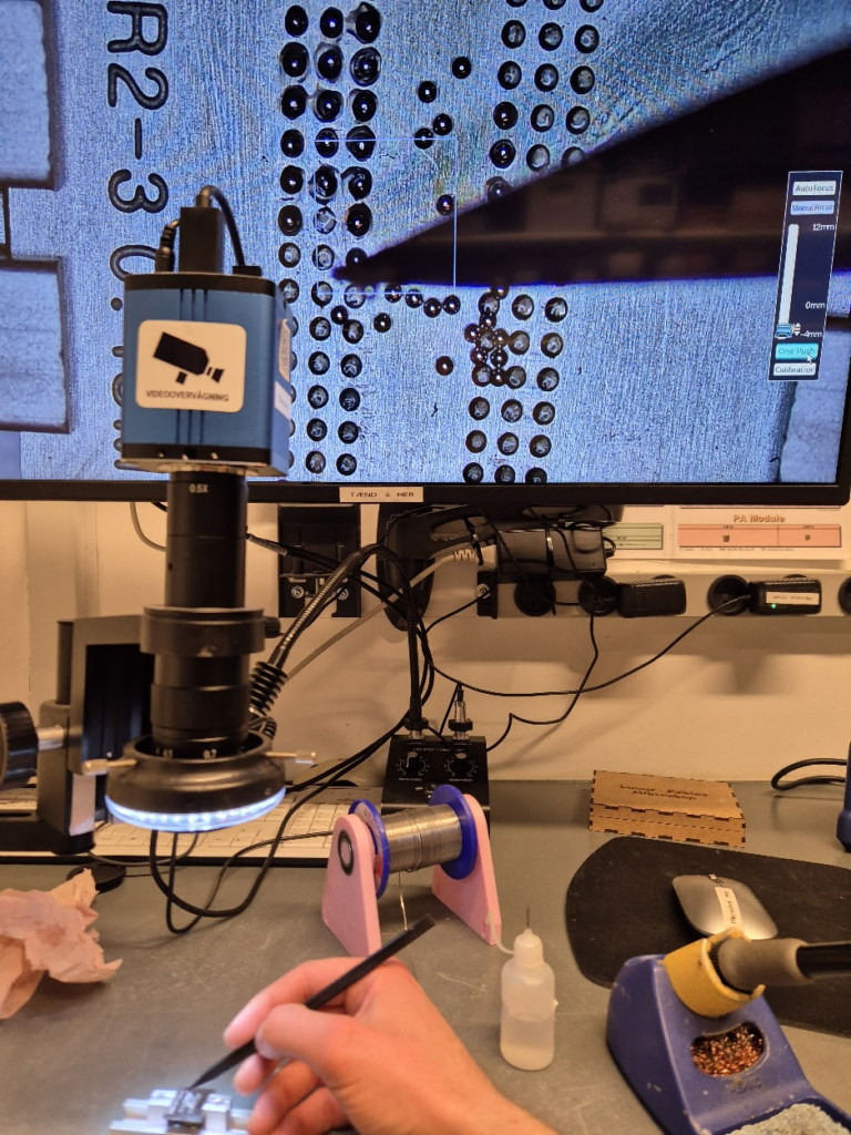
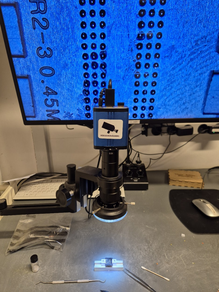
Learning to BGA solder
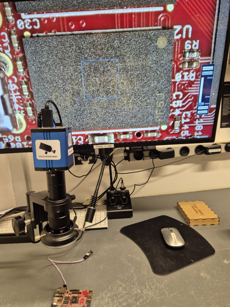
Finally, we can jump to the microscope soldering station, and learn to BGA solder. This was by far the longest part of this project. The chips come pre-balled, so in theory the job could have been as simple as desoldering the old chips and soldering on the new ones. Not so easy in practice. I ended up having to re-ball and re-solder chips, apply flux, solder-wick and ethanol in copious amount, re-attach SMD resistors that had taken a stroll under the heatgun, and battling a self-compiled U-Boot that I probably messed up badly. You get to see my frustration in a few nice pictures.
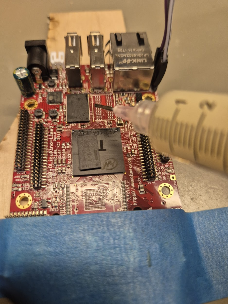
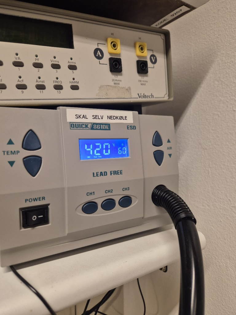
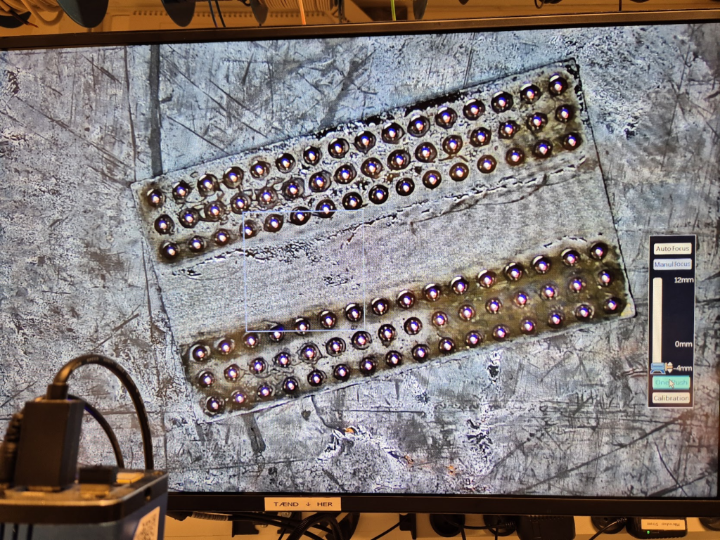
I have a suspicion that I messed up U-Boot at one point, by trying to compile it with automatic impedance calibration, instead of leaving the LIME2 defaults DDR settings in. This might be the reason I couldn’t get the Micron MT41K512M16 chips to work, but I will have to investigate this more. I probably also messed up the first soldering on of a chip, by not using enough heat. My main piece of advice would be to not be too afraid to get the temperature of the chip up, if you spend more than about a minute trying to solder or desolder the chip, chances are you will be heating up the rest of the board much more than needed and the chip itself too little!
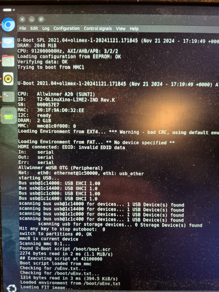
The moment of seeing the board booting with 1GB from a single ISSI IS46TR16512BL was a great success though — soldering on the other ISSI chip was basically a walk in the park.
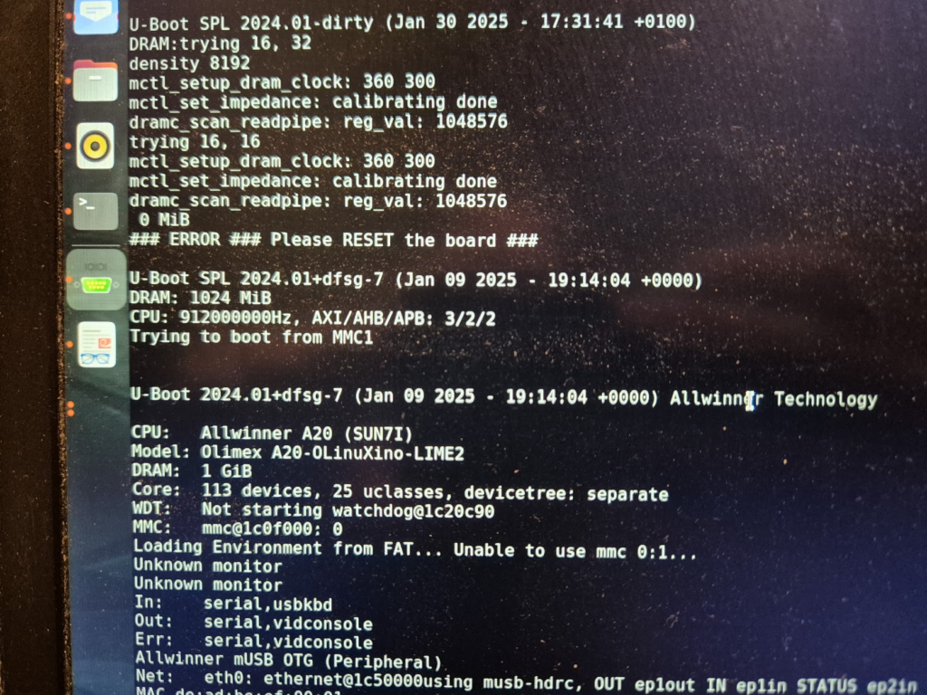
Further U-Boot adventures of a curious character
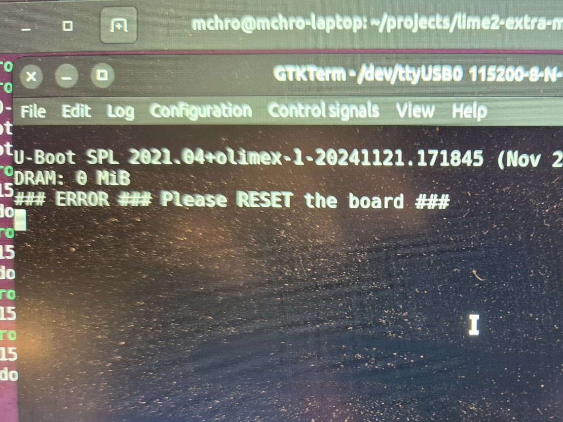
A serial terminal is absolutely essential for getting any kind of feedback on the early part of the boot process, and the first user-controlled software encountered on the LIME2 is U-Boot. U-Boot is the universal bootloader responsible for figuring out the basic hardware configuration (including RAM configuration), finding the (Linux) kernel and moving it into RAM and giving over control to the kernel for further booting. Curiously, U-Boot can run with absolutely no RAM chips (guess how I know!), because the SunXi early boot process happens entirely in on-chip ROM and a small on-chip SRAM.
But how does U-Boot actually determine how much memory is there? Well, remember that accessing a memory location is just putting an address on the address lines and pulling some signalling pins. So U-Boot simply tries and write to increasing addresses and see if the expected data can be read back. How is the memory size then communicated to the Linux kernel? By a bootarg parameter, e.g. mem=2048M. Does this mean we can try and trick the Linux kernel into thinking it has more memory than physically present? Yes, but with disastrous results if the non-existent memory is ever attempted to be used.
I now possess a unique 2GB LIME2
Until told otherwise, I will happily claim that this is the only 2GB LIME2 in existence — but do let me know if you give the procedure a try! In the end the process was much simpler than I thought: the tricky part was definitely getting the hang of BGA soldering. Don’t be afraid of raising the temperature! Peeking into the innards of U-Boot was also fascinating: there is definitely a layer below of pretty dark bit-setting magic, but the overall process is really well structured!
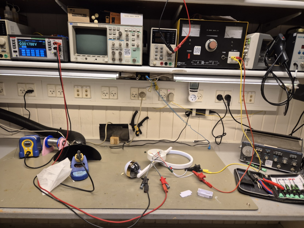
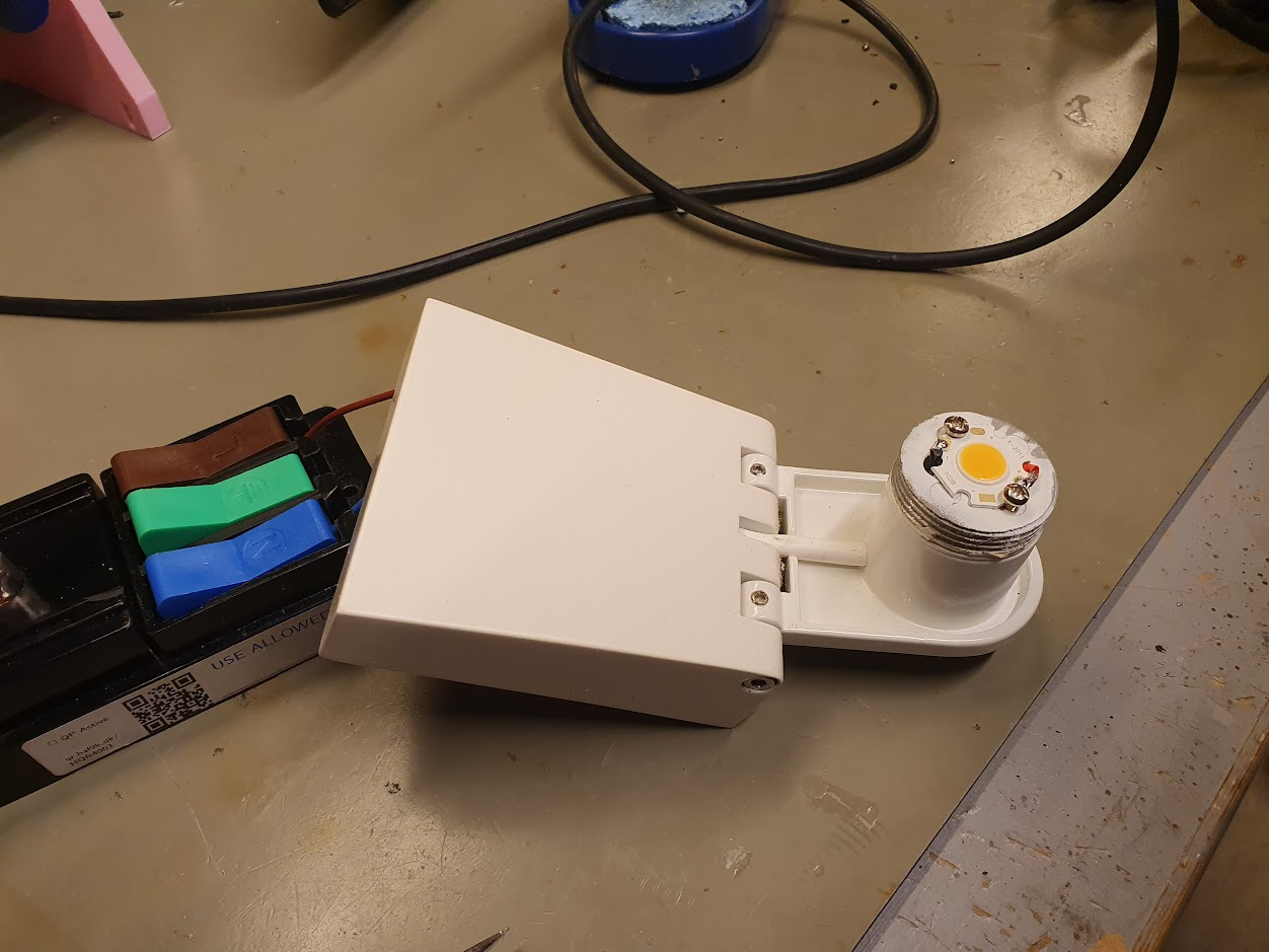
Making a too cheap LED lamp safe to use
This could happen to you: A really cool LED lamp was found online, on a Danish and well-written homepage. Unfortunately, when the lamp arrives it is a cheap Chinese production, of questionable quality and safety. This is a non-rational quest to make such a cheap LED lamp safe to use.
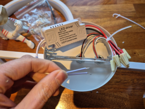
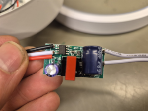
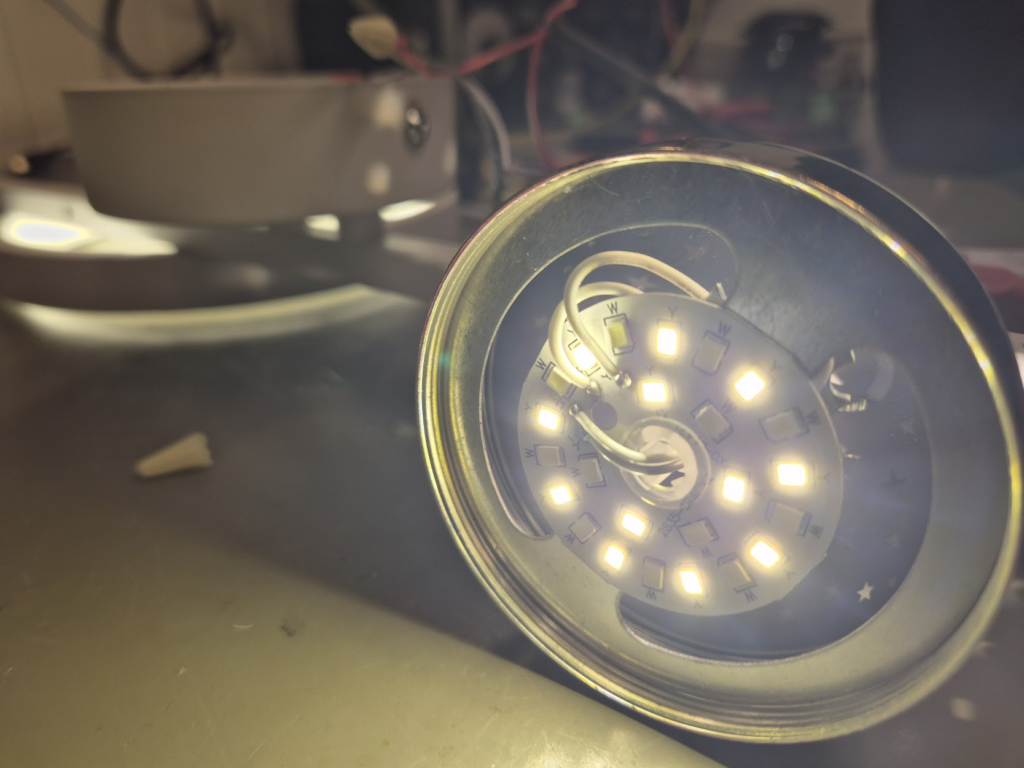
From the outset the wires are tiny. The wires are connected with wire nuts *gasp*! (Wire nuts are basically unheard of in Europe). The LED driver itself that converts the 230V AC into DC has absolutely no separation, and as we will see later, absolutely no safety features. It did have a cool feature of changing light color temperature by turning the lamp on and off a couple of times, though.
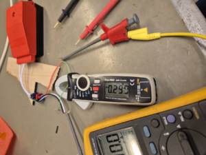
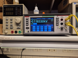
But happily going to 300mA when shorted, going up to 118V unloaded, and full willingness to spark away, is a deal-breaker. This abomination was not being powered on in this house! It should be possible to replace the unsafe parts with safer (and more expensive) parts.
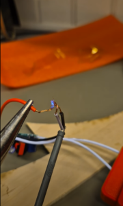
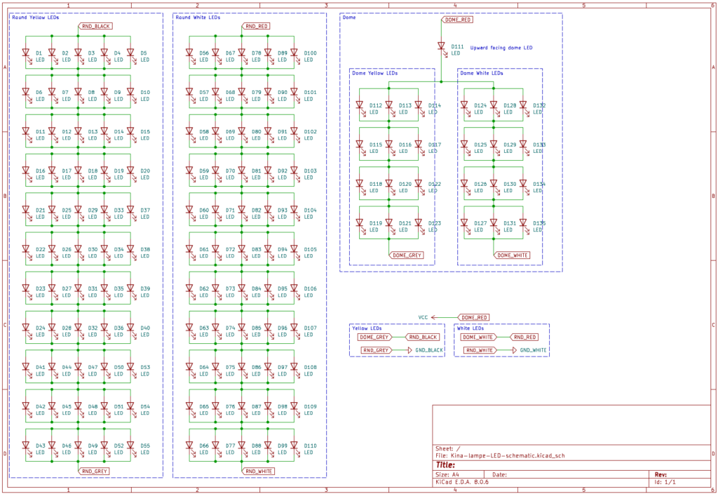
The first step was understanding the mess of wires. This took quite some pondering to figure out that all the LEDs were basically in series, and that it was wired with a “common positive”, with either the white or the black wire (or both) acting as ground depending on the wanted color temperature.
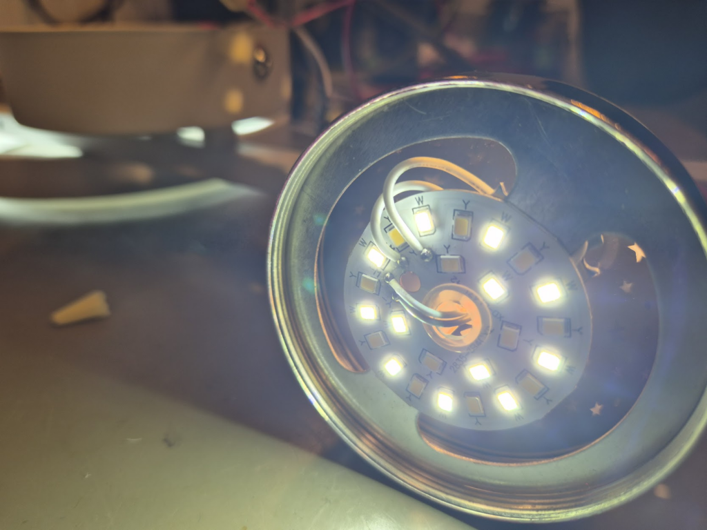
In the end the entire schematic was reverse engineered.
That LED driver was going nowhere but the electronic garbage bin, so a replacement of decent quality had to be acquired: a constant-current LED driver (configurable from 200mA–350mA) was purchased from a reputable source. That gave the next problem: an LED driver of quality was at least double the size of the unsafe one, and did not fit in the original round enclosure. 3D-printing to the rescue, and a new bigger round enclosure was printed.
Now everything should be able to fit and work! Instead of that illogical wiring of putting the LEDs in series, why not just put the two parts in parallel? Well, that won’t work. Only the path of least-resistance would light up, in this case the dome LEDs. So, back to the original wiring in series.
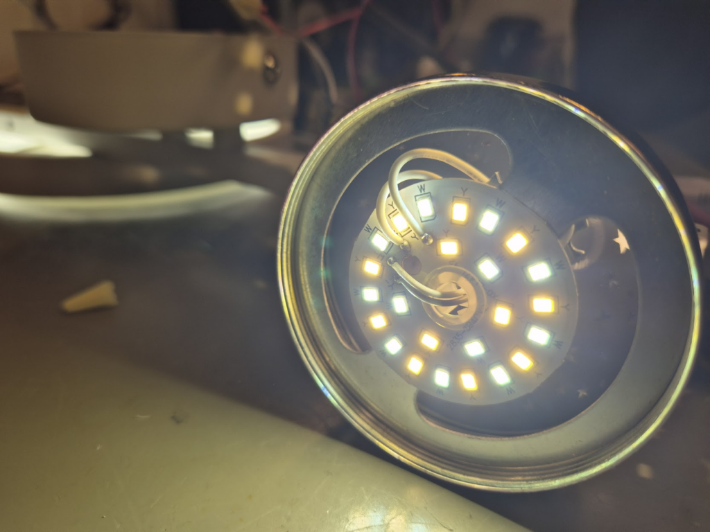
Unfortunately, the next problem was that the new LED driver was unwilling to drive LEDs as originally wired, that seemed to require somewhere above 45V, out of spec for the new driver. More stuff had to change. Looking at the schematic, the long strip in the circle could be cut in half, and the two half put in parallel instead. This should reduce the power going to those LEDs, and thus also the light output, but should also help to decrease the required voltage. But first I had to learn again the hard way that putting LEDs in parallel they need to match quite closely: the original LED strip had 11 segments, and dividing into 6 and 5 gave lights only in the one part.
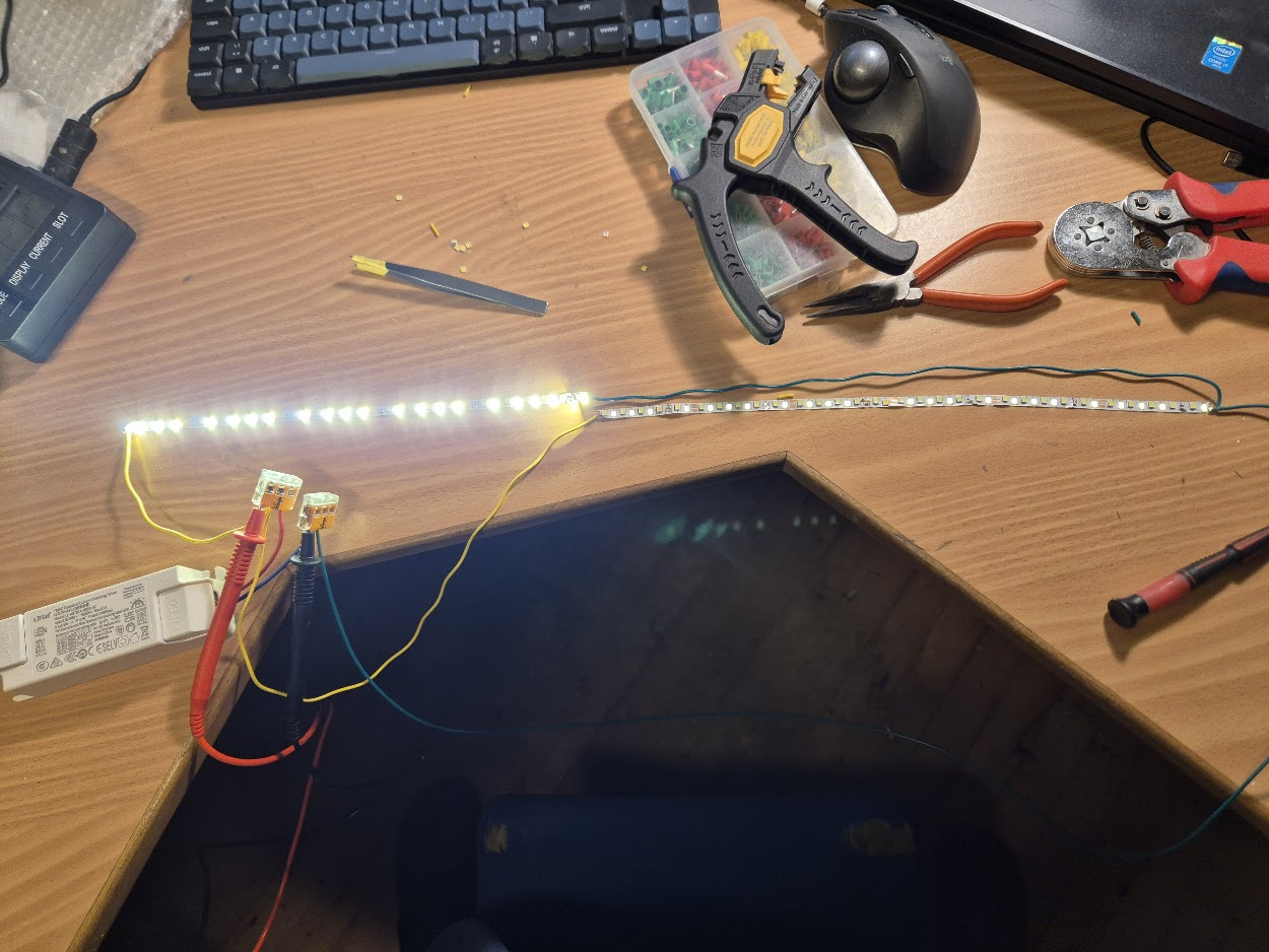
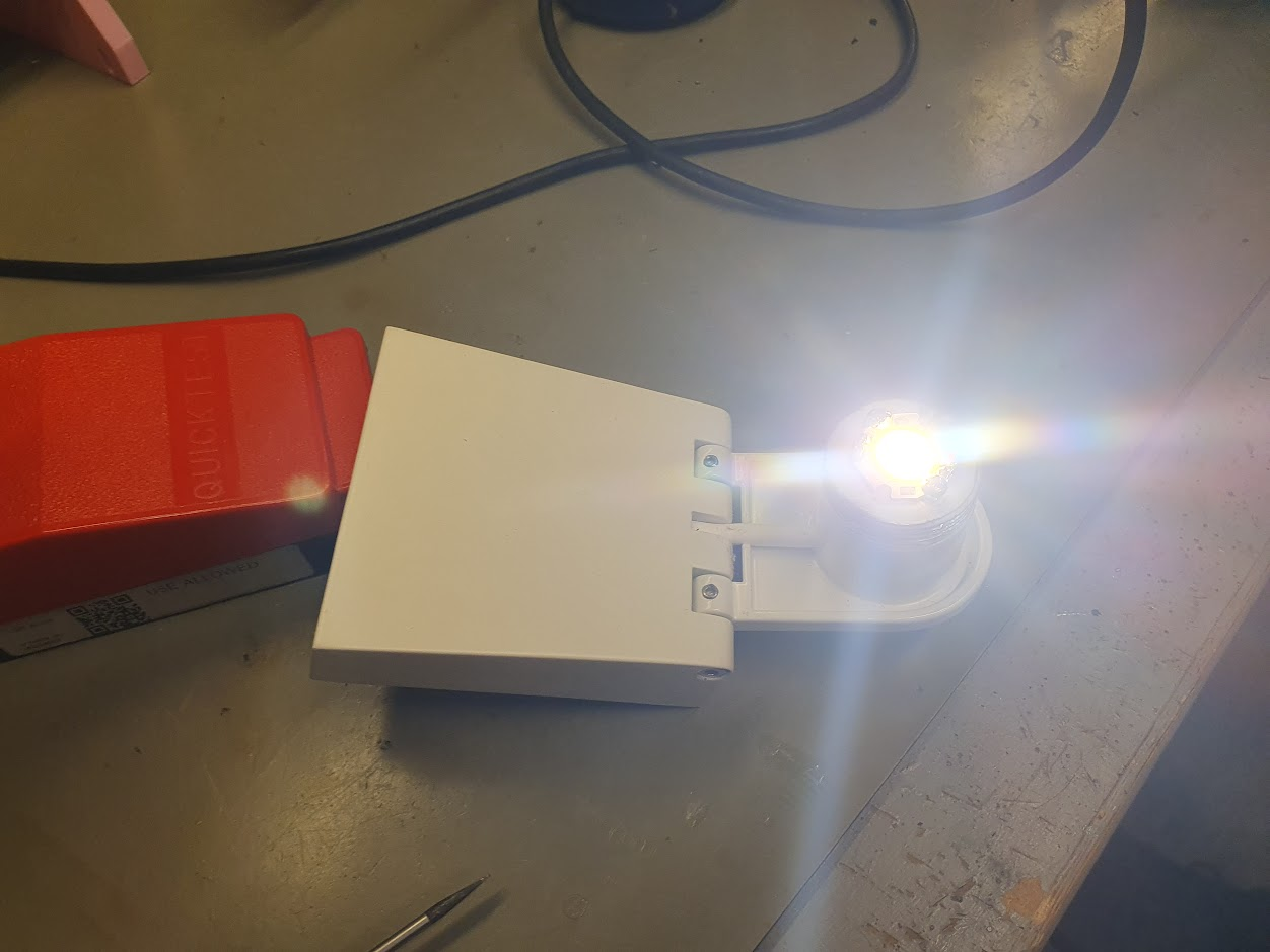
Reducing to 5 and 5 segments worked really well!
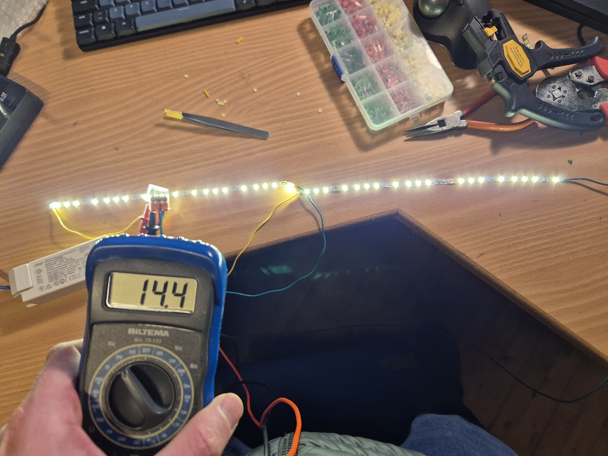
Finally, the total voltage of putting the two parts of the lamp in series was below what the new LED driver would supply.
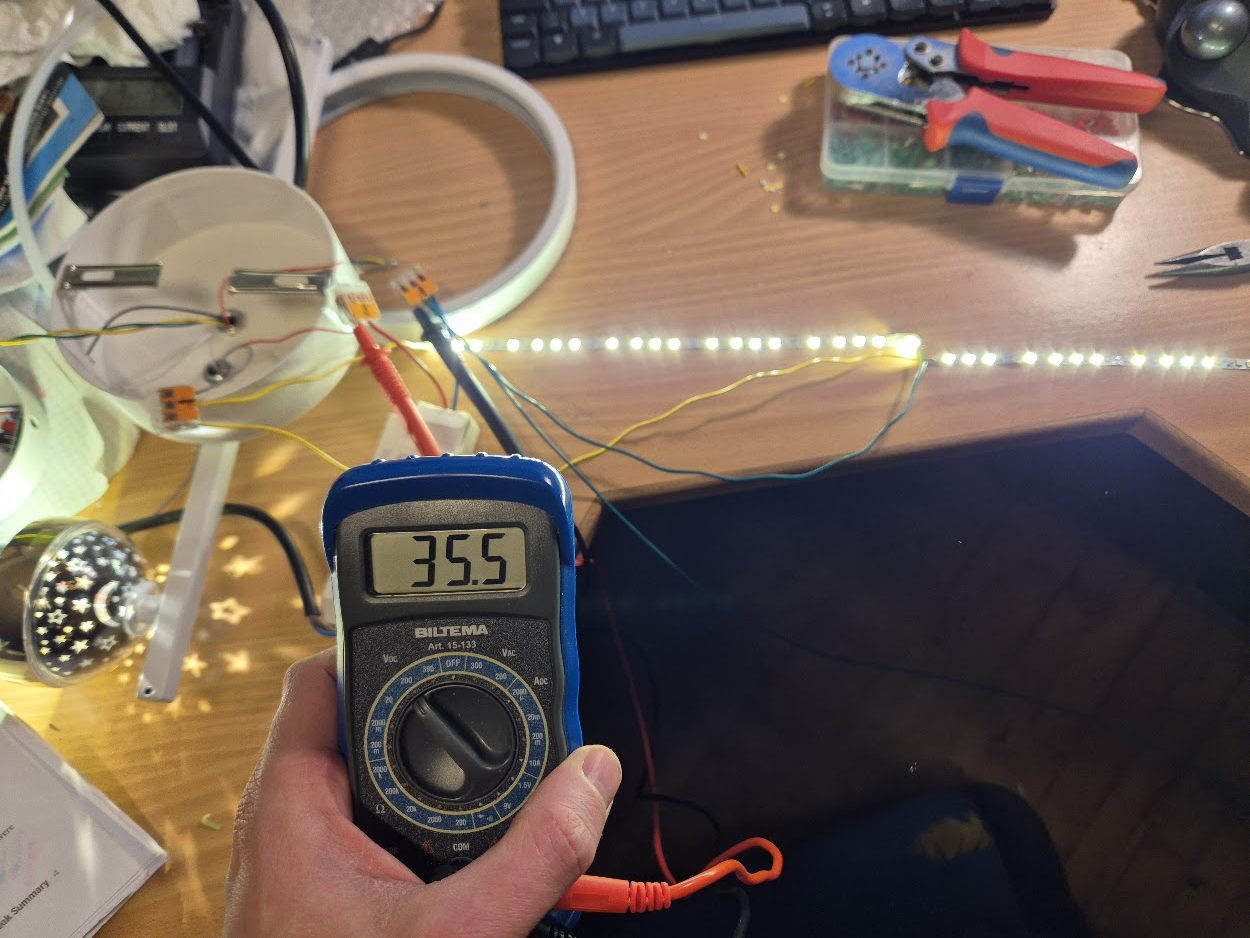
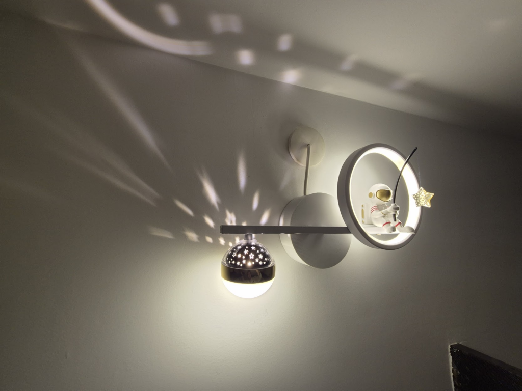
The only task remaining was to fit everything back into the enclosure, and add copious amounts of Kapton tape and hot glue. And finally, the spaceman could go star-fishing – safely.
Giv mig nu bare elprisen.somjson.dk! (en historie om det måske værste datasæt i åbne energidata)
Der findes rigtig meget åbent data om det danske energi system hos Energi Data Service, f.x. spot prisen på elektricitet og CO2 prognoser per kWh. Det er dog overordentligt svært at finde den samlede pris man betaler som forbruger per kWh, pga. det uigennemskuelige datasæt over tariffer og priser. I frustration kom udbruddet: “Giv mig nu bare elprisen.somjson.dk” der nemt summerer alle priser og afgiter per elselskab, er open source og uden yderligere dikke-darer.
Hvad koster strøm i Danmark?
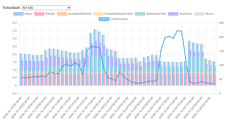
For en forbruger i Danmark er strømprisen en sum af forskellige priser og afgifter, nogle faste, nogle dynamiske:
- El-afgiften fastsat ved lov til 0,761 kr per kWh.
- Energinet’s eltariffer: Nettarif på 0,074 kr per kWh (år 2024), og systemtarif på 0,051 kr per kWh (år 2024).
- Netselskabstarif fra forsyningsselskabet (N1, Radius, etc.): denne varierer per time og per sæson for at forsøge at incentivere til at udligne forbruget så der ikke skal investeres i nye og større elkabler, og er indkodet i datasættet over tariffer og priser. Private forbrugere betaler C-tarif.
- Spot-prisen: er den anden variable, og denne varierer ud fra udbud og efterspørgsel.
- Moms: 25% lagt til summen af ovenstående
Dette er alle de uundgåelige priser og afgifter, der kan regnes ud udelukkende fra adressen. Derudover kommer så det “frie elmarked”, hvor der skal betales til et elselskab: typisk månedsabonnement og et tillæg til spot-prisen.
Tariffer og priser – det værste åbne datasæt?
Som om det ikke er uoverskueligt nok i sig selv, bliver vi nødt til at snakke om datasættet Datahub Price List. Der er flere åbenlyse problemer med det:
- Der er flere felter man burde filtrere efter, men hvor der ikke findes en udtømmende liste over værdier, f.x. netselskab “ChargeOwner”. Det bedste man kan gøre er at downloade, hvor man så løber ind i at download kun giver 100.000 rækker – og datasættet er fuldt på over 300.000 rækker.
- ChargeTypeCode er per selskab – og uden systematik. Så for hvert enkelt selskab skal man finde ud af hvilken priskode de bruger for C-tariffen. Og hvad når det ændrer sig?
- ValidTo kan være udeladt og dermed et open ended interval, og prisen gælder så indtil data retroaktivt ændres. Det betyder også at man ikke kan filtrere på datoer, da prisen på 1. april kan være en række der har en ValidFrom 1. januar (eller tidligere).
- Price1-24: dette er selve timetarif-priserne. Hvis en pris ikke er udfyldt gælder Price1 – hvorfor I alverden dog tilføje den ekstra kompleksitet!?!?!
- For ikke at tale om tidszoner: man må antage (det er ikke dokumenteret) at alle datoer og timetal er angivet i hvad end tid der er gældende i Danmark på pågældende dato. Dette giver så problemer ved skift fra sommer-/normal-tid hvor en time gentages eller udelades: hvilken timesats bør bruges i et døgn der har 23 eller 25 timer?
Giv mig nu bare elprisen.somjson.dk!
Efter at have regnet de fleste af de ovenstående problemer ud, skrev jeg en API-proxy der udstiller det API man i virkeligheden vil have: givet en dato, og et elselskab (eller en adresse), returnerer den prisen time for time som et JSON dokument. Prisen er typisk tilgængelig fra kl. 13 dagen før. Som bonus får man også CO2 udledningen med, hvis den er tilgængelig (typisk kl. 15 dagen før). Det er implementeret som en ren API proxy, dvs. det er ren omskrivning af input og data og ikke andet.
Det hele er open source, men der kører en version på elprisen.somjson.dk som frit kan benyttes.
Alternativer
Der findes andre API’er der opfylder forskellige use-cases:
- Min Strøm API er rigtig modent og har egen forecast model der kan forecaste 7 dage frem, før priserne er låst på Energi Data Service. Kræver en API nøgle og er uden kildekode
- HomeAssistant energidataservice virker kun med Home Assistant, men fungerer på samme måde mod Energi Data Service.
- Strømligning API kan bruges til at udregne priser baseret på historisk forbrugsdata. Kan dog også bruges til at hente de forecastede priser. Med rate limiting, og uden kildekode.
- Carnot har også et åbent API og egen forecast model. Kræver API nøgle, og er uden kildekode.
- Billigkwh.dk har et åbent API til elpriser der også inkluderer de forskellige elselskabers abonnement.
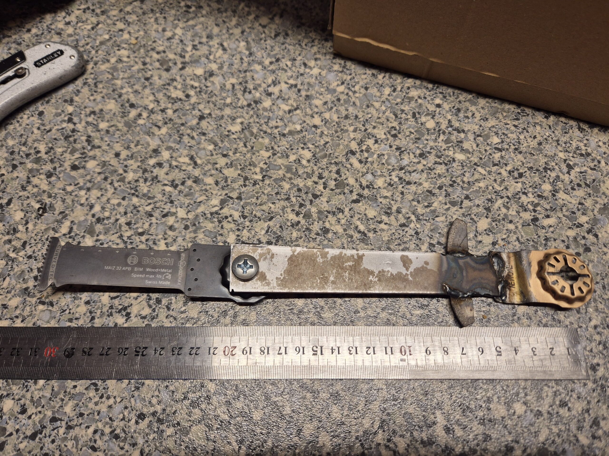
World’s Longest Multi-Cutter Blade: 30 cm
I had a need for an extra-extra long multi-cutter blade, so we made one in Hal9k. Until proven otherwise, we hereby claim it to be the world’s longest, at about 30 cm from rotation point to the cutting edge.
Converting Starlock-MAX to Starlock-Plus
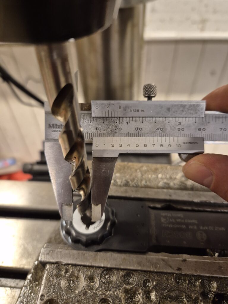
Initially I thought I could get away with just a 80mm long Bosch MAIZ 32 APB which seems to be the longest commercially available. First problem was that my multi-cutter was only “Starlock-Plus” and this blade is Starlock-MAX. Turns out, you can easily get around that: just drill up the hole to 10mm, and it fits like a glove, at least on the Starlock-Plus Bosch GOP 18V-28.
World record time
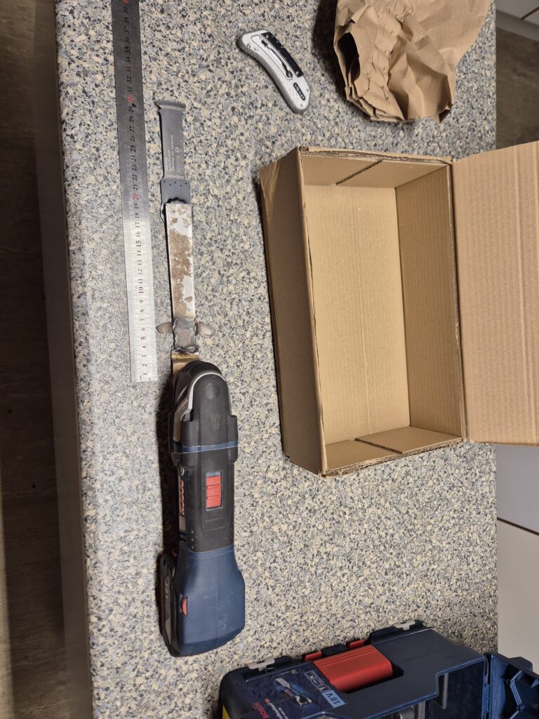
But as it turns out, I needed more length, and anything worth doing is worth overkilling! So sacrificing an old worn-out blade by welding on some 2mm steel plate provided a good base that would still attach to the multi-cutter.


First attempt was just attaching the blade with two 2mm screws, as these are the largest that will fit in the star’s spikes and thereby prevent rotation. Initial testing:
So next solution was to beef up with a central 8mm bolt instead.
This worked much better if torqued enough (read: all you possibly can!), test-run went great after the initial oscillations:
And ultimately the cut in the tight corner was made, one-handedly in order to be able to film:
Great success!
This should not be considered safe, and several warranties were probably voided, but it got the job done.
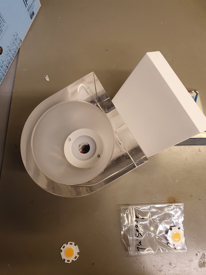
Reparation af Nordlux IP S12 badeværelseslampe der ikke lyser længere
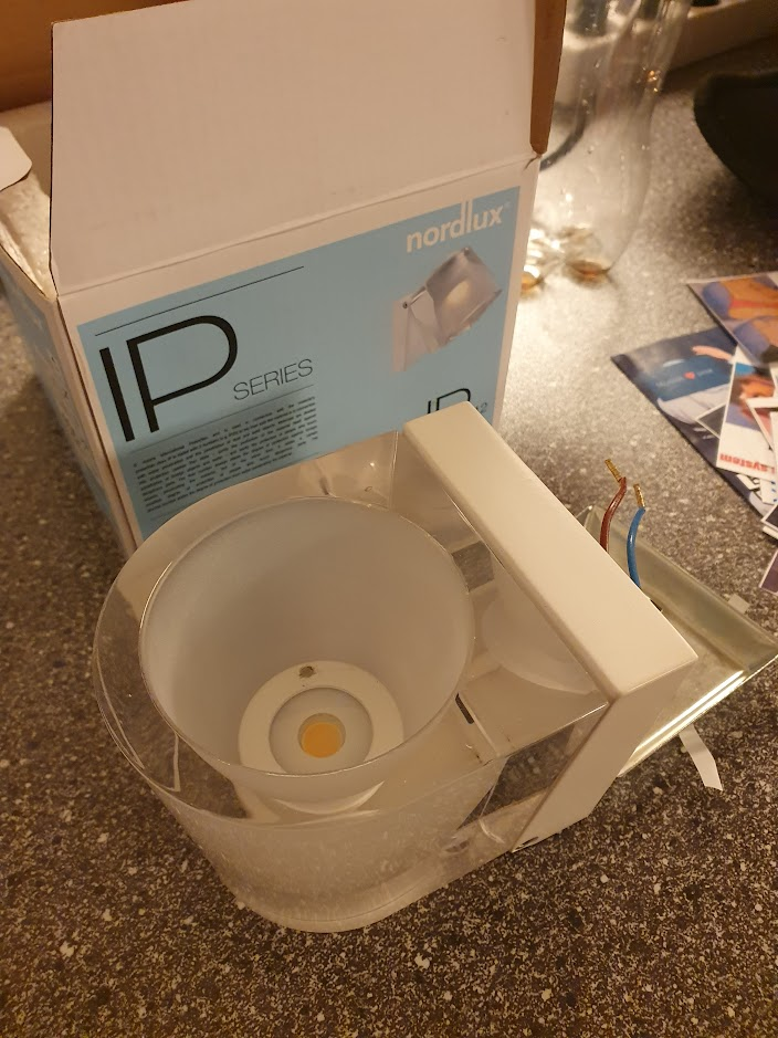
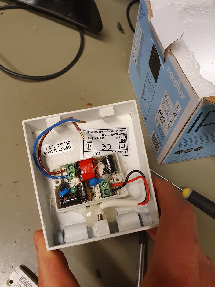
Denne badeværelseslampe er udgået af produktion, og pga. monteringen og at man ofte har mere end én er det noget træls at skulle udskifte – det giver ihvertfald en del skrot uden grund. Heldigvis er konstruktionen super simpel: det er udelukkende en LED driver (230V AC til 24V DC) og en LED.
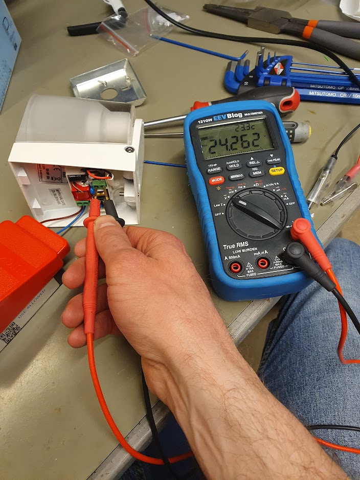
Lad os starte med det nemme: LED-driveren er direkte tilgængelig bagfra, og med lidt forsigtighed kan spændingen udmåles. I dette tilfælde var der ca. 24V DC, og det er jo fint indenfor specifikationen.
Selve LED’en er lidt sværere at komme til: fronten af glasset skal drejes af via de to huller deri. Jeg brugte en låseringstang af ca. korrekt dimension, med lidt forsigtighed. Lidt ridser gør nok ikke det store når lyset skinner. LED’en kan nu loddes af.
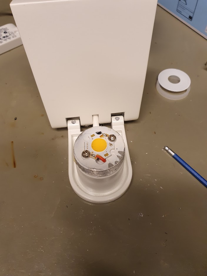
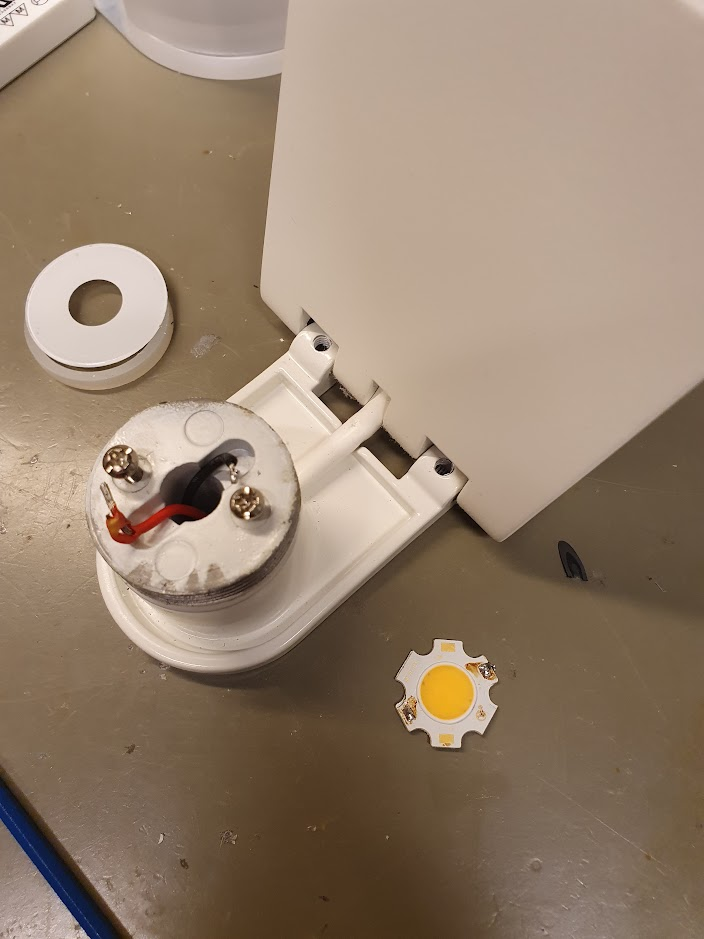
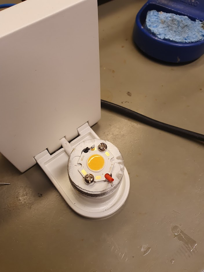
En ny LED kan købes for ca. 10 kr, f.x. på AliExpress. Det rigtige søgterm er måske “Bridgelux 2020 COB LED”, jeg endte med en 7W i Warm White (3000 Kelvin).
Efter lidt fidlen og lodden er den nye LED monteret, og kan testes. Stor succes!
Fantus-button part 2: the physical button build and the network communication
First part of this series is here, covering the reverse engineering of the DRTV Chromecast App.
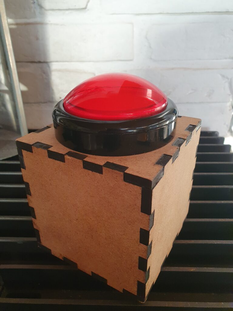
I wanted the physical appearance to be extremely minimalistic, with slight references to various cubes from videogames. Because it is a remote control, it of course has to be wireless and battery-powered.
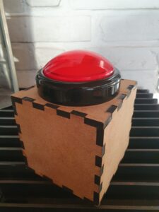
The box is lasercut from 6 mm MDF, and with a giant red arcade button on top with a red LED inside.
The electronics inside is a battery-powered Wemos D1, along with 4 x 18650 Lithium battery cells. After some experimentation on the response time, which is primarily dominated by the time it takes to reconnect to the WiFi network, I initially only used “light sleep”. This resulted in a battery time of just over a week, which is okay, but not great.
In order to preserve battery deep sleep would be really nice. The problem is deep sleep on the Wemos can only be interrupted by a reset. The idea was to use a MOSFET (in this case an N-channel logic level mosfet, IRFZ44N) for the Wemos to be able to select whether a press of the button should reset it, or it should just register on a pin as normal.
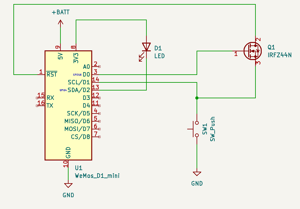
This circuit allows RST to be pulled low by the button, as long as D0 is high. Luckily, D0 is high during deep sleep, so as long as the Arduino code keeps D0 low button presses will not reset — but can still be registered by reading pin D1.
This works out “responsively enough” because the initial start has some delay due to the Chromecast initializing the app and loading media. Any subsequent button presses within the 30 seconds the Arduino stays awake are instant though. With this setup the battery life is not a problem – I’ve only had to charge it once. As a bonus feature/bug whenever the battery gets low the Wemos will trigger a bit sporadically: this causes “Fantus-bombing” where Fantus will just randomly start; quite quickly thereafter the Fantus-button is being charged 😉
The Wemos itself is not powerful enough to do all the pyChromecast communication needed, so I setup a small Raspberry Pi to handle that part. Since I didn’t want to spend too much time and effort setting up the communication between them, I ended up using a trick from my youth: UDP broadcasting. Because UDP is datagram-oriented you can send a UDP packet to the broadcast address (255.255.255.255) and then it will be received by all hosts on the local area network: no configuration needed. In Arduino code it looks like:
  Udp.begin(31337);
  Udp.beginPacket("255.255.255.255", 31337);
  Udp.write("emergency-button\n");
Udp.endPacket();(Full Arduino code available here.)
At this point I had a UDP packet that I could receive on the Raspberry Pi, and it was just a matter of writing a small server program to listen, receive and process those UDP commands. However, at this point a thought entered my mind, that derailed the project for a while:
netcat | bash
Why write my own server to parse and execute commands, when Bash is already fully capable of doing exactly that with more flexibility than I could ever dream of? And netcat is perfectly capable of receiving UDP packets? This is a UNIX system, after all, and UNIX is all about combining simple commands in pipelines — each doing one thing well.
The diabolical simplicity of just executing commands directly from the network was a bit too insecure though. This is where Bash Restricted mode enters the project: I wouldn’t rely on it for high security (since it is trying to “enumerate badness“), but by locking down the PATH of commands that are allowed to execute it should be relatively safe from most of the common bypass techniques:
netcat -u -k -l 31337 | PATH=./handlers/ /bin/bash -rThe project was now fully working: press the button, Fantus starts. Press it while Fantus is playing: Fantus pauses. Press it while Fantus is paused: Fantus resumes. The little human was delighted about his new powers over the world, and pressed the button to his hearts content (and his parents slight annoyance at times).
(Full code for handler available here.)
But wouldn’t it be cool if the little human had a (limited) choice in what to view?…
Fantus-button part 1: Reverse engineering the DRTV Chromecast App
I want to build a physical giant red button, that when pressed instantly starts a children’s TV-show, in my case Fantus on DRTV using a Chromecast.
The first part of the build is figuring out how to remotely start a specific video on a Chromecast. Initially I thought this would be pretty simple to do from an Arduino, because back in the day you could start a video just using a HTTP request. Very much not so anymore: the Chromecast protocol has evolved into some monster using JSON inside Protobuf over TLS/TCP, with multicast DNS for discovery. Chance of getting that working on a microcontroller is near-zero.
But remote control is possible using e.g. pychromecast which has support for not only the usual app of YouTube, but also a couple of custom ones like BBC. Let’s try and add support for DRTV to pychromecast, starting at the hints given on adding a new app.
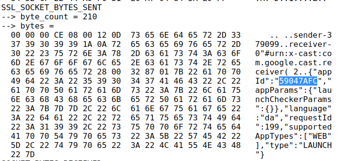
Using the netlog-viewer to decode the captured net-export from Chrome, and looking at the unencrypted socket communication, the appId of the DRTV app is easily found.
However, one of the subsequent commands has a lot more customData than I expected, since it should more or less just be the contentId that is needed:
{
  "items": [
    {
      "autoplay": true,
      "customData": {
        "accountToken": {
          "expirationDate": "2022-07-02T00:48:35.391Z",
          "geoLocation": "dk",
          "isCountryVerified": false,
          "isDeviceAbroad": false,
          "isFallbackToken": false,
          "isOptedOut": false,
          "profileId": "c4e0...f3e",
          "refreshable": true,
          "scope": "Catalog",
          "type": "UserAccount",
          "value": "eyJ0eX...Dh8kXg"
        },
        "chainPlayCountdown": 10,
        "profileToken": {
          "expirationDate": "2022-07-02T00:48:35.389Z",
          "geoLocation": "dk",
          "isCountryVerified": false,
          "isDeviceAbroad": false,
          "isFallbackToken": false,
          "isOptedOut": false,
          "profileId": "c4e0a...f3e",
          "refreshable": true,
          "scope": "Catalog",
          "type": "UserProfile",
          "value": "eyJ0eXAi...IkWOU5TA"
        },
        "senderAppVersion": "2.211.33",
        "senderDeviceType": "web_browser",
        "sessionId": "cd84eb44-bce0-495b-ab6a-41ef125b945d",
        "showDebugOverlay": false,
        "userId": ""
      },
      "media": {
        "contentId": "278091",
        "contentType": "video/hls",
        "customData": {
          "accessService": "StandardVideo"
        },
        "streamType": "BUFFERED"
      },
      "preloadTime": 0,
      "startTime": 0
    }
  ],
  "repeatMode": "REPEAT_OFF",
  "requestId": 202,
  "sessionId": "81bdf716-f28a-485b-8dc3-ac4881346f79",
  "startIndex": 0,
  "type": "QUEUE_LOAD"
}
Here I spent a long time trying without any customData, and just using the appId and contentId. Initially it seemed to work!
However, it turned out it only worked if the DRTV Chromecast app was already launched from another device. If launched directly from pychromecast the app would load, show a spinner, and then go back to idle. Here much frustration was spent; I guess the customData is actually needed. And indeed, putting that in works! But where do these tokens come from, and how do we get those tokens from Python?
Using Chrome’s developer tools (F12) on the DRTV page, and then searching globally (CTRL-SHIFT-f) for various terms (“expirationDate”, “customData”, “profileToken”, “accountToken” etc.) revealed some interesting code, that was as semi-readable as any pretty-printed minifyed Javascript. Eventually I found the tokens in local storage:
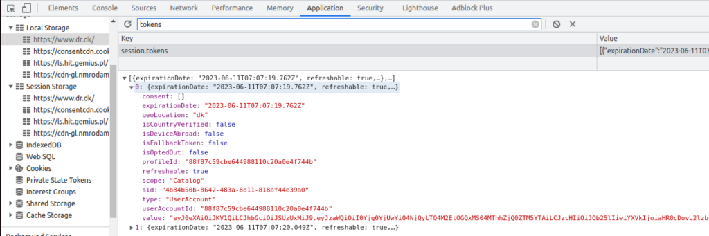
Using these tokens work really well, and allows starting playback!
Some further exploration proceeded: using the showDebugOverlay flag reveals that the DRTV player is just a rebranded Shaka Player. The autoplay functionality can be disabled by setting chainPlayCountdown to -1, which is honestly a real oversight that it cannot be disabled officially, to not have to rush to stop the playback of the item before the next autoplays.
With all the puzzle pieces ready, I prepared a pull request (still open) to add support for DRTV to pychromecast.
Fantus-button part 2 will follow, detailing the hardware build and network integration with the support from pychromecast.
Floating Solid Wood Alcove Shelves
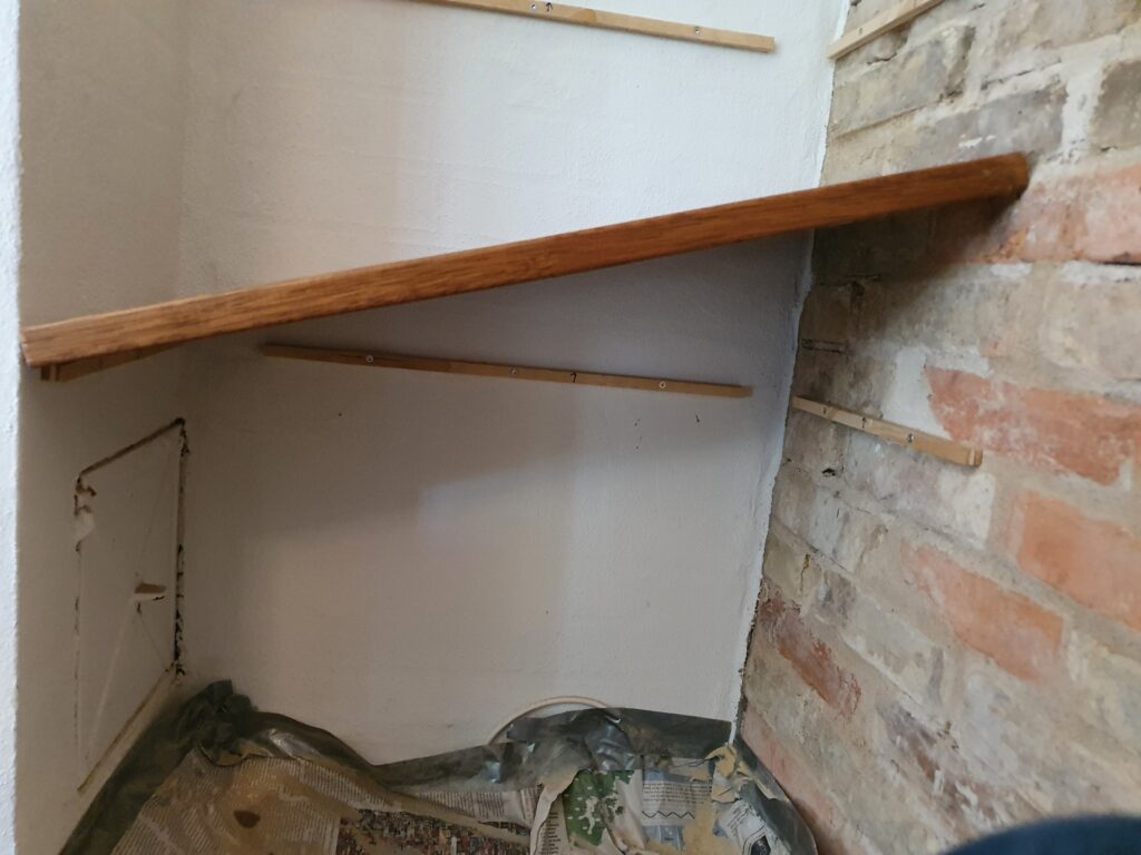
I have an alcove where I wanted to put in some floating shelves. I wanted to use some solid wood I had lying around, to match the rest of the interior; this ruled out most of the methods described online: (i) building up the shelf around a bracket, and (ii) using hidden mounting hardware would be hard to get precise and would not provide support on the sides.
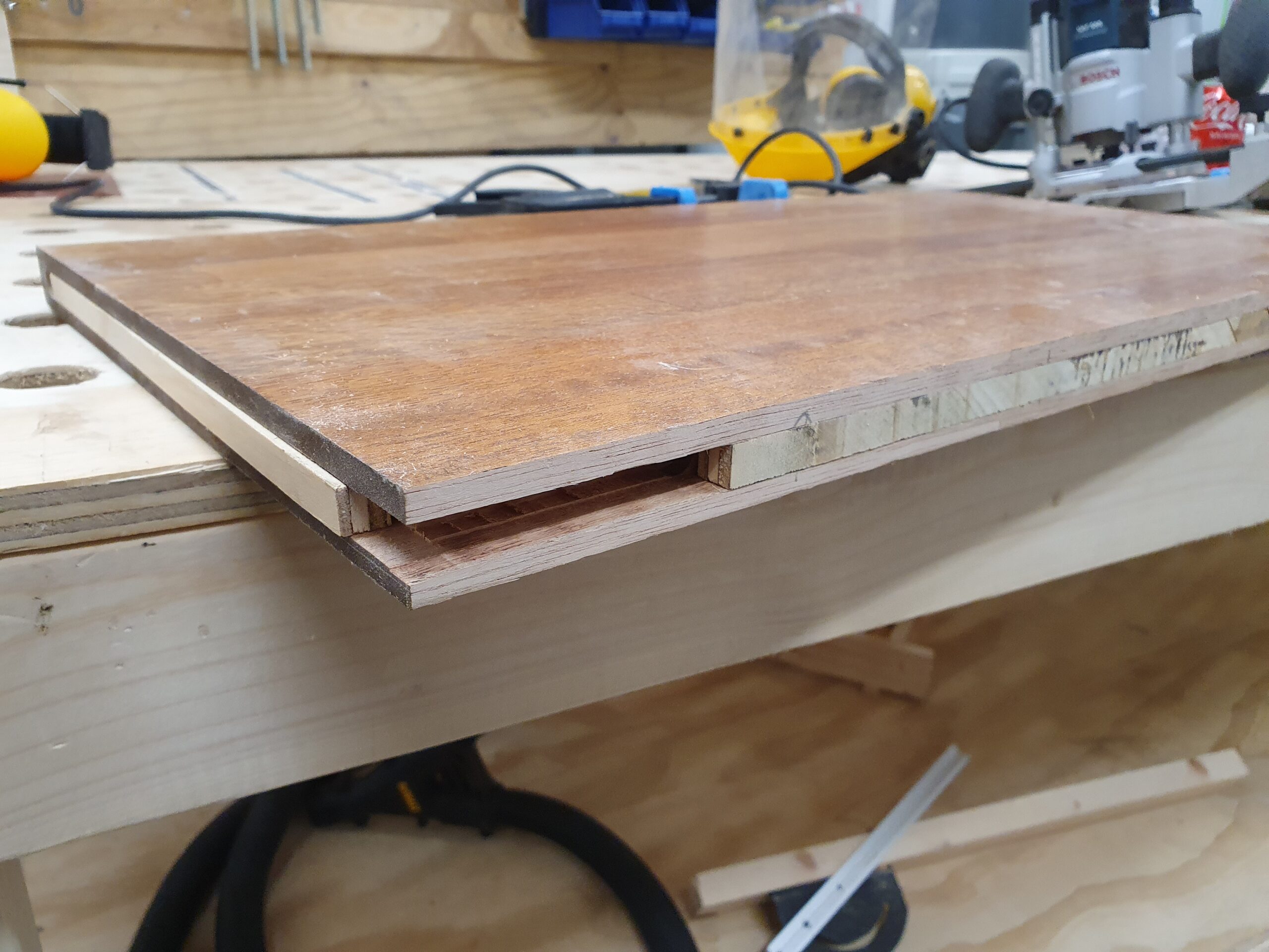
So inspired by some of the options instead I tried to get by with just brackets on the three sides, in a solid wood shelf. I ended up with 12mm brackets of plywood in a 26mm solid wood shelf, and that was plenty sturdy.
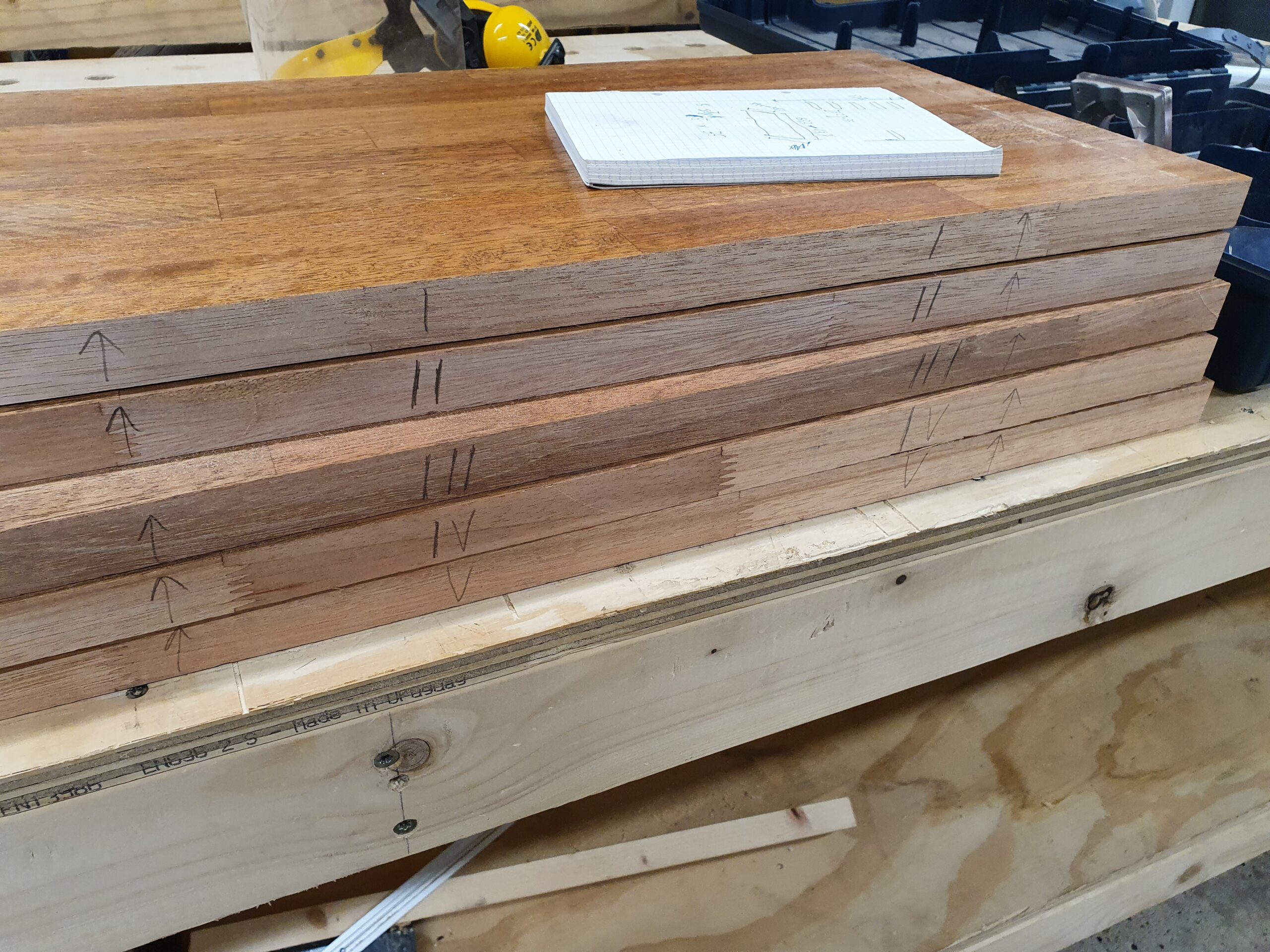
Step 1 was to cut out the rough shelves, with plenty of extra width, and rough fitting the plywood bracket pieces. It makes sense to leave as much on the top of the slit as possible, as this will be the failure point if overloaded. The excellent wood workshop at Hal9k came in very handy!

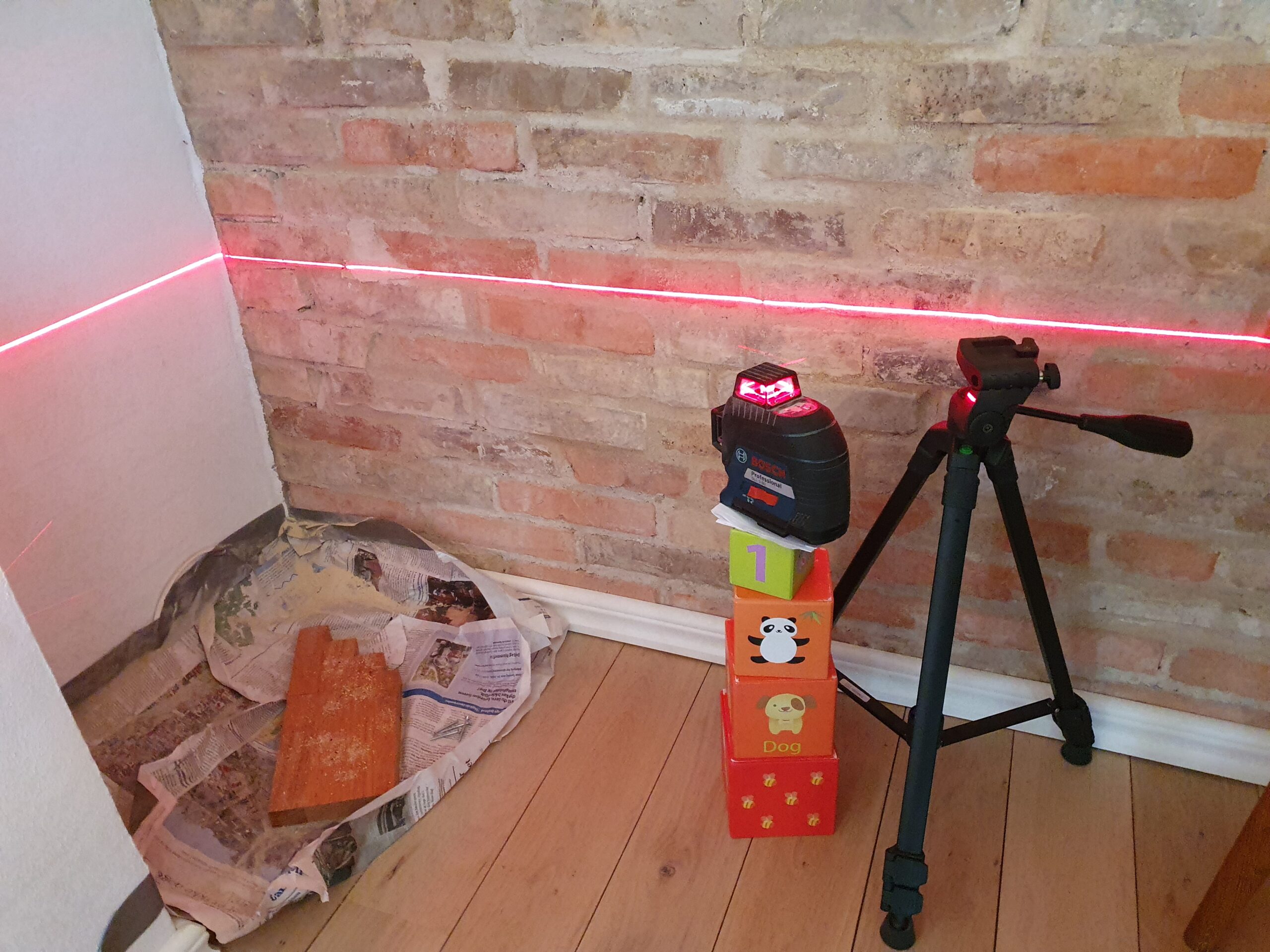
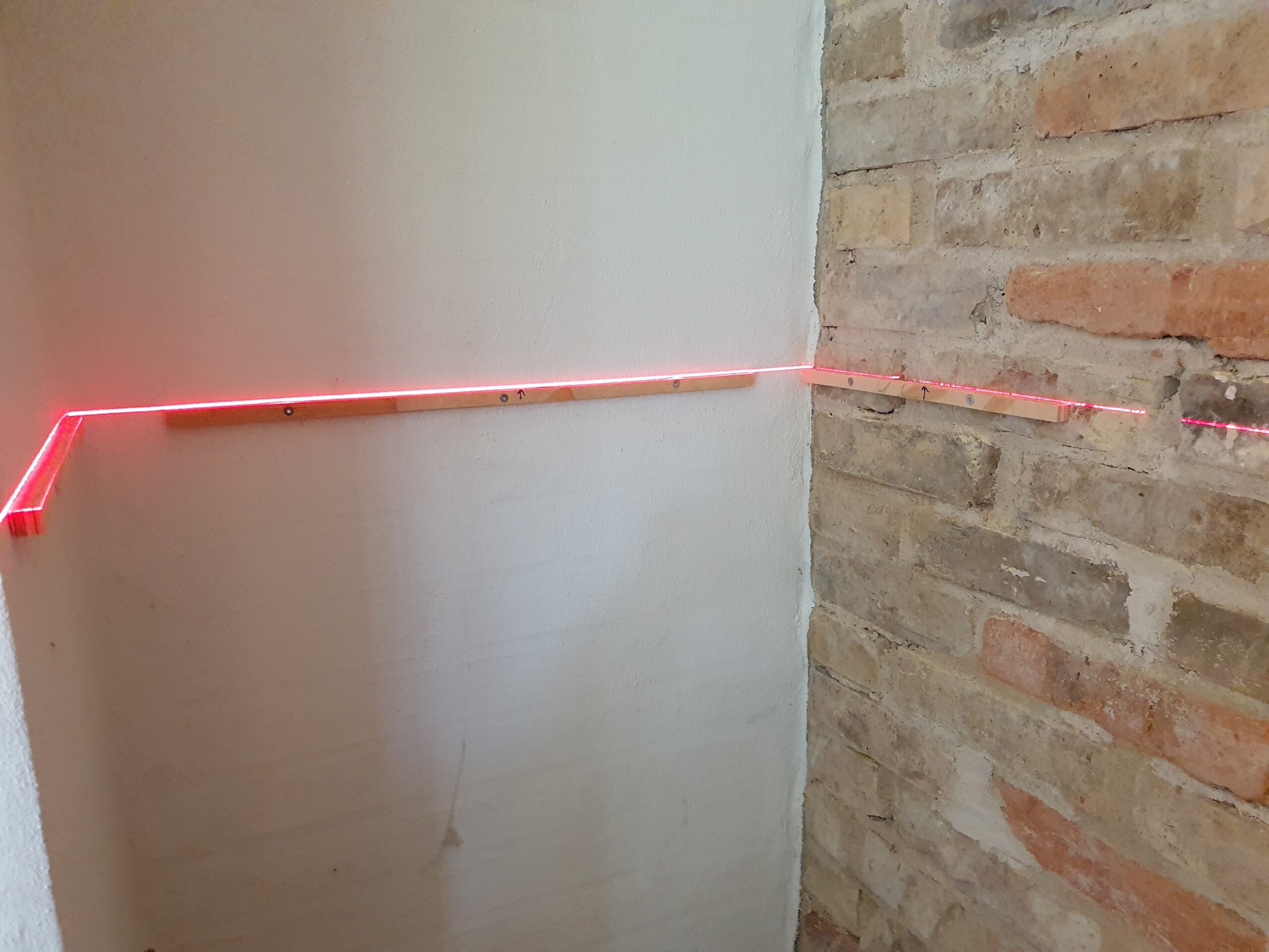
Step 2 was to mount the plywood brackets in the alcove. Pretty easy to do using a laser level, biggest problem was getting the rawplugs in precise enough for the level to be kept.
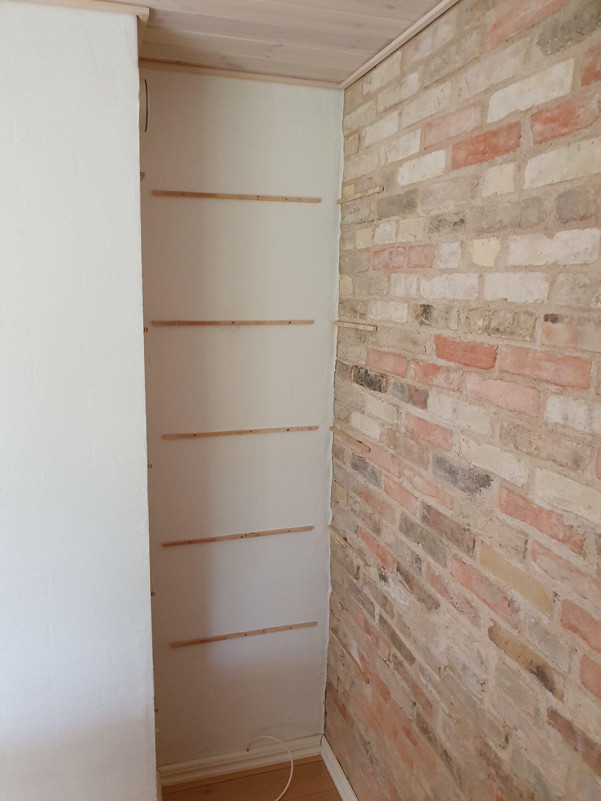
Step 3 was fitting the shelves individually, accounting for the crookedness of the 3 walls. The scribing method used by Rag’n’Bone Brown was pretty useful, just doing it in multiple steps to make sure not to cut off too much.
Finally, all the shelves in final mounting. Getting them in took a bit of persuasion with a hammer, and minor adjustments with a knife to the plywood brackets, as it was a tight fit. The key again was small adjustments.
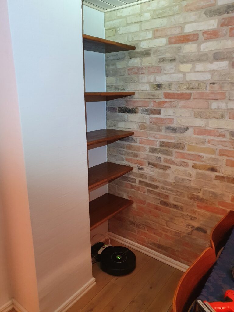
One concern with such a tight fit would be wood movement; however most of the wood movement is “across the grain” which in this application means “in and out” from the alcove, where the wood is basically free to move as the shelves are not fastened to the brackets in any way.
Another concern would be if the relatively small brackets (12x12mm) can handle the load of the relatively wide shelves (60cm wide, 35cm deep, and 2.6cm high). There are two failure scenarios: (i) the wood could split above the slit, (ii) or the bracket could deform or be pulled out. Neither seems likely as (i) applying a static (or even dynamic) load large enough to split the wood seems implausible, even at the weakest point in the middle of the front, and (ii) the tight fit counteracts the brackets ability to be pulled out since pulling out in one side would have the shelf hitting the wall on the opposite side.
All in all a very satisfying project to work on and complete!
Quick and dirty guide to Lithium battery-powered Wemos D1 Mini
The Wemos D1 Mini is an ESP8266 based prototyping board with WiFi connectivity and countless applications. It becomes even more useful in battery-powered applications, where with the proper setup, it can run low-powered for months at a time — or only hours if done incorrectly.
This is the quick and dirty guide to running a Wemos D1 Mini powered by Lithium-Ion batteries: We will be blatantly ignoring several design specifications, so double check everything before using in a critical project. Several things will vary, and since there is plenty of clones of the board some boards will work better than others.
Warning: Lithium-Ion batteries always command healthy respect, due to the energy they store! Do not use bad cells, and do not leave batteries unattended in places where a fire can develop, especially while charging. That being said, the setup given here should be as safe as most other Lithium-Ion battery projects.
Why run off a battery?
You chose a Wemos D1 because you want to do some WiFi connectivity. This narrows down the useful modes from the overwhelming large table of possibilities. The approach will be slightly different depending on why you want to run off a battery. There are 3 main usecases:
- Periodically wake up on a timer, do some work, connect to WiFi, and go back to sleep. Here we can utilize the deep sleep mode of the ESP8266, and get lifetimes in months.
- Wake up based on an external pin trigger, do some work, connect to WiFi, and go back to sleep. Here we can also utilize deep sleep, and get lifetimes in weeks/months.
- React with low latency to an external pin, do some work, and go to sleep while still connected to WiFi. Here we can utilize light sleep, but only get lifetimes in hours/days.
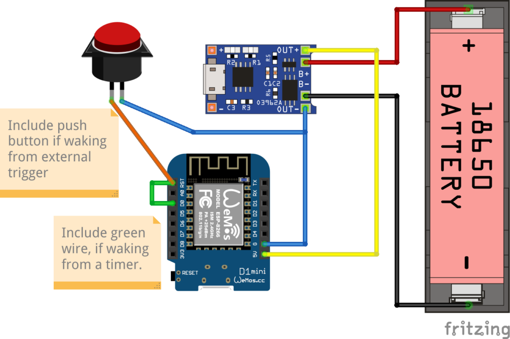
Hardware setup
The hardware needed is:
- Wemos D1 Mini
- TP4056 module with “discharge protection”, most modules with more than one chip has this, but be careful!
- Lithium-Ion battery, e.g. a 18650 cell, and probably a holder for the battery
What you don’t want is anything resembling a power bank or battery shield with a regulated output (5V or 3V). These are practically useless, simply a more expensive battery holder! Two reasons: poorly built (I have several where standby is prevented by pulling 100 mA through a resistor!), and you don’t want a switching mode power supply. The keyword here is “quiescent current”: an SMPS can easily consume 5-10 mA continuously, which could very likely be the majority of the current draw.
Waking on a timer – deep sleep
Full code example for deep sleeping on a timer.
To start deep sleep for a specified period of time:
//Sleep for some time; when waking everything will be reset and setup() will run again
ESP.deepSleep(30 * MICROSECONDS_PER_SEC);
Note that you can’t safely sleep for more than approximately 3 hours. Power usage is approx 0.3–0.4mA when deep sleeping.
Keep in mind that after waking from the timer the chip will be reset, meaning no state is available, and WiFi will have to reconnect. Reconnecting to WiFi can be anything from 3–10 seconds or even longer, meaning that will be a delay before the program can resume.
Waking on an pin trigger (reset)
Full code example for deep sleeping waiting for a pin trigger.
The code is exactly the same as waking on a timer, with one exception:
//Sleep until RESET pin is triggered
ESP.deepSleep(0);
The chip will be effectively comatose, sleeping until a RESET is triggered. Same caveats apply: waking up the program is restarted, and reconnecting to WiFi will be a delay.
Stay connected – low latency
Full code example for light sleeping connected to WiFi waiting for a pin trigger. Note that the button should be connected to D3 for this example, not RST.
The key parts are:
void setup() {
  ...
  WiFi.setSleepMode(WIFI_LIGHT_SLEEP, 3);  // Automatic Light Sleep
}

void loop() {
  ...
  delay(350); // Any value between 100--500 will work, higher value more power savings
    // but also slower wakeup!
}
Simply delaying will bring power savings — simple and easy!
When awake power consumption is around 75mA. Average power consumption when light sleeping with delay(200) is around 45 mA, with delay(350) and larger is around 30–40mA.
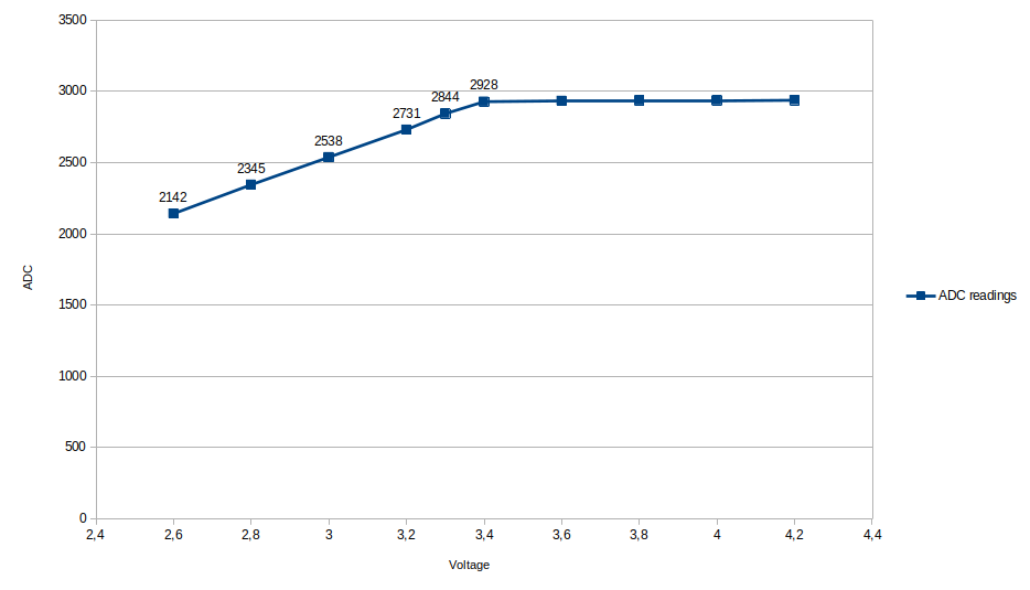
Measuring battery depletion
The ESP can measure it’s internal VCC supply voltage, and because the battery will start dropping below the rated 3.3V before it is depleted, this allows to get an warning when the battery starts to deplete.
ADC_MODE(ADC_VCC);

void loop() {
  if (ESP.getVcc() < 2800) {
    //Do something to warn of low battery
  }
}
In my experience the Vcc reading will drop below 2800 when the battery starts to be depleted.
Note that measuring the VCC while connected with USB is not possible, as the USB connection will pull up the battery and the 5V rail to 5V!
Calculating battery life
Here is a quick calculator for how long your Wemos D1 Mini can stay powered
Deep sleep
(conservatively assumes base load 1mA, 10 secs burst of 100mA for every wakeup), resulting in
–
Light sleep
–
Of course the consumption can be brought even lower: some chips are unused but partly connected and will have some leakage (LEDs, USB chip on the Wemos). Making it even leaner is outside the scope of quick and dirty.