
Hvorfor korrelerer min DC-spænding med solen?

I mit home-monitoring setup har jeg en AC-DC strømforsyning der laver DC-strøm og lader UPS-batterierne. Denne spænding overvåger jeg, som beskrevet i sidste blogindlæg. Grafen set for en typisk dag ser ud som ovenover. Der er en tydelig stigning i spændingen om morgenen og et tydeligt fald sidst på eftermiddagen. Det korrelerer forbavsende godt med hvornår solen står og og går ned. Her er data for 3 forskellige dage, overlagt med sol op-/ned-tidspunkt:
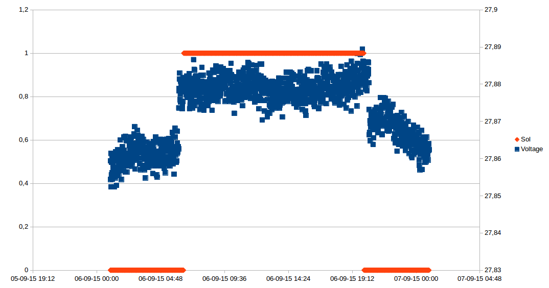
6. september – ufiltreret
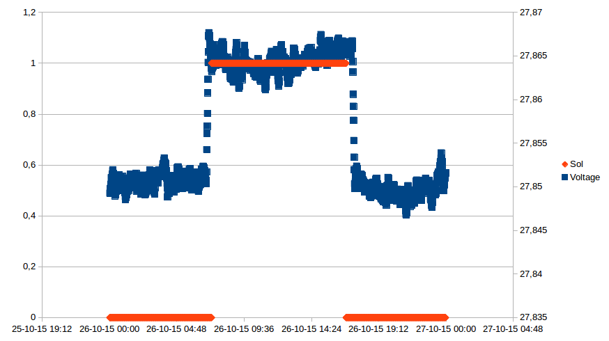
26. oktober – filtreret
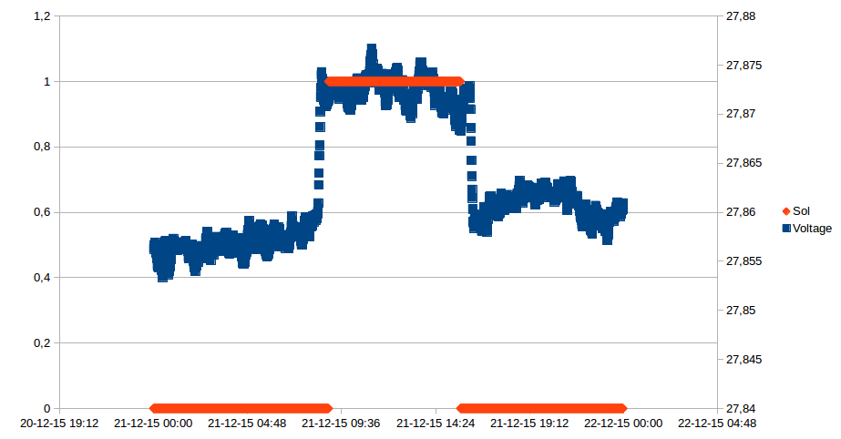
21. december – filtreret
Der er ikke noget forbundet til DC-forsyningen der trækker væsentlig forskellig strøm efter belastning (det der er forbundet er switche, router og Arduinoer), og intet der tænder/slukker efter tidspunktet. Temperaturen varierer ikke væsentligt i rack-skabet, og korrelerer ikke med spændingen:
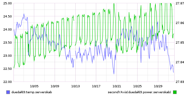
Temperatur og spænding, hele oktober. Spænding (grøn) på højre akse.
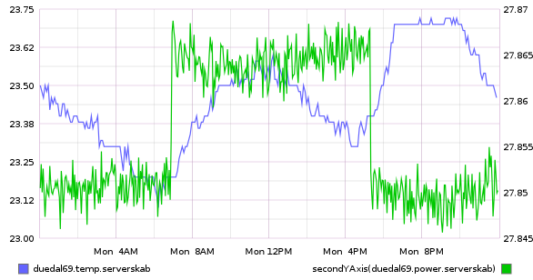
Temperatur og spænding, 26. oktober. Spænding (grøn) på højre akse.
Så det store spørgsmål er: Hvorfor korrelerer min DC-spænding med solen? Er det pga. solceller i nabolaget? Er det pga. gadebelysning der tænder/slukker? Gode bud modtages 🙂
Measuring high DC supply voltage with an Arduino
For my home-monitoring setup I would like an Arduino to measure the supply voltage it is getting from a DC battery UPS (Uninteruptible Power Supply). Unfortunately (actually by design, but that’s another story), the power supply is 24V, which means it will put out anywhere from 21.3V-29.8V (according to the manufacturer), which is far too much to measure with the Arduino’s 0-5V input range. For simplicity’s sake, lets assume we want to measure a 20-30V voltage.
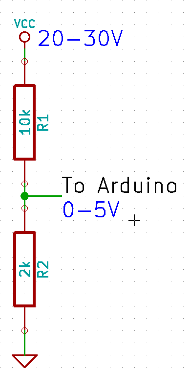
The immediate answer is to use a voltage divider, which will bring a voltage in the 0-30V range into the 0-5V range. The general formula for the resistor divider is:
![\[V_{out} = \frac{R_2}{R_1+R_2} \cdot V_{in}\]](https://blog.smartere.dk/wp-content/ql-cache/quicklatex.com-ee1f44dbd85a1cd2218265ee49ce5255_l3.png "Rendered by QuickLaTeX.com")
We want  to give
  , so
, so
![\[\frac{5}{30} = \frac{R_2}{R_1+R_2}\]](https://blog.smartere.dk/wp-content/ql-cache/quicklatex.com-f02f447533b604db627794c4ebd6140b_l3.png "Rendered by QuickLaTeX.com")
Now, just as a sanity check we should calculate the current of the resistor divider, to make sure we’re not converting too much electricity into heat. Ohm’s law gives us
![\[ I = \frac{U}{R}\]](https://blog.smartere.dk/wp-content/ql-cache/quicklatex.com-93017fbe68496cbd35e880ea8ee1c4b5_l3.png "Rendered by QuickLaTeX.com")
which in this cases gives
![\[ I = \frac{30}{12000} = 0.0025 A = 2.5 mA\]](https://blog.smartere.dk/wp-content/ql-cache/quicklatex.com-6631b393a242838c08feb147241b12dd_l3.png "Rendered by QuickLaTeX.com")
No problems there.
This works okay, but we lose a lot of precision, as only ~1/3 of the Arduino’s range is actually used: the Arduino’s ADC has 1024 different readings between 0-5V, so when reading the 0-30V range the precision is just about
 over the range.
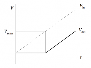
If only we could move the lower bound, so that 20V would map to 0V on the Arduino. A wild Zener Diode appears! One use of a Zener diode is as a voltage shifter.
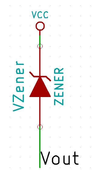
Zener diode voltage shifter
The closest Zener diode I could find was an 18V of the BZX79 series. This resulted in the following circuit:
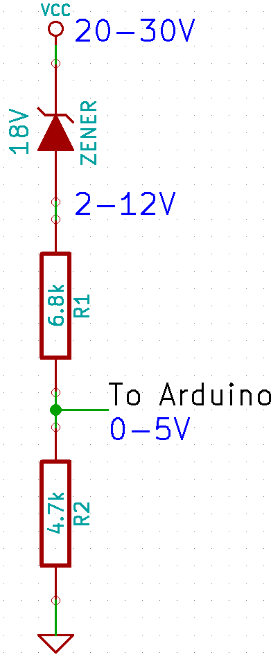
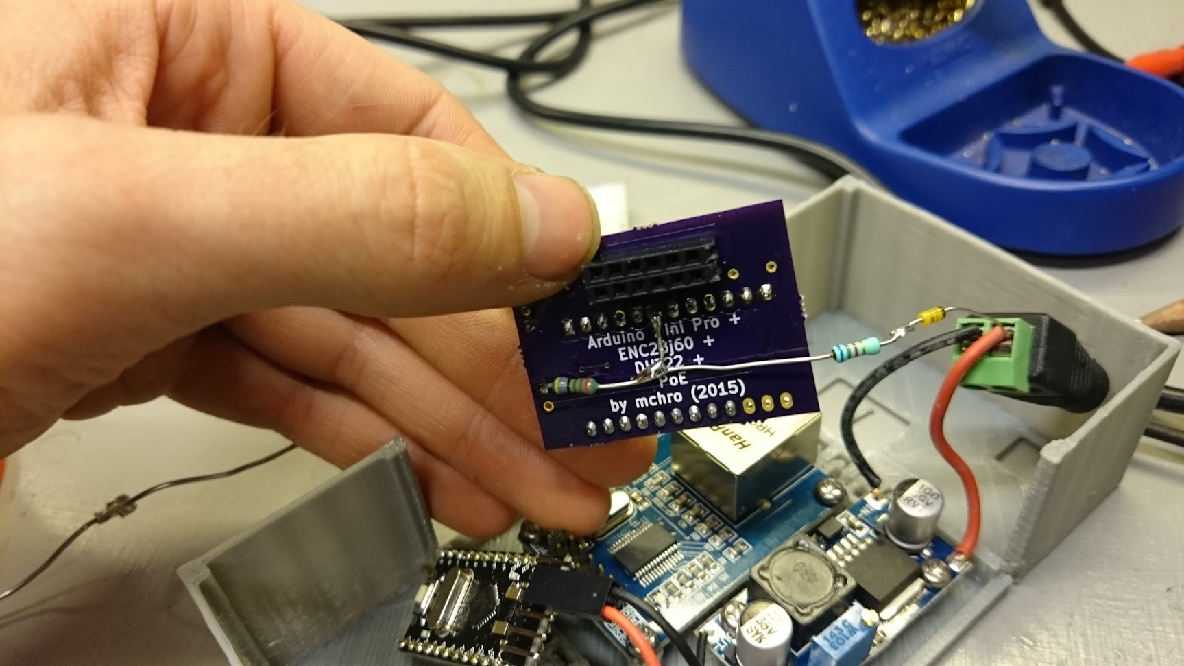
which I hacked into my Arduino box.
Now, theoretically the formula for translating an voltage at the Arduino to the supply voltage should be:
![\[Vcc = V_{in} / (4700/(4700+6800)) + 18 = V_{in} \cdot 2.4468 + 18\]](https://blog.smartere.dk/wp-content/ql-cache/quicklatex.com-2bf301ad44061de9fd4492ef666f33ad_l3.png "Rendered by QuickLaTeX.com")
I then did some quick measurements of various input voltages and the resulting voltage at the Arduino pin:
| Input voltage | Arduino pin |
| 18V | 0.32V |
| 20V | 1.16V |
| 26V | 3.60V |
| 28V | 4.41V |
| 29V | 4.81V |
Plot it into a spreadsheet, create a graph and add a linear regression gives:
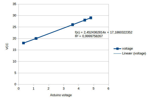
Now, this formula is a bit different compared to the theoretical one, mainly in the Zener diode drop. However, the datasheet for the BZX79 actually has the 18V C-type ( ) as between 16.8-19.1V, so this is well within spec. Since this is just a one-off, I’m happy to just use the measured formula, as this will be more accurate.
The final precision should be  . The current should be around
  , which again is ok.
Roomba 500-series Easy Scheduling using an Arduino
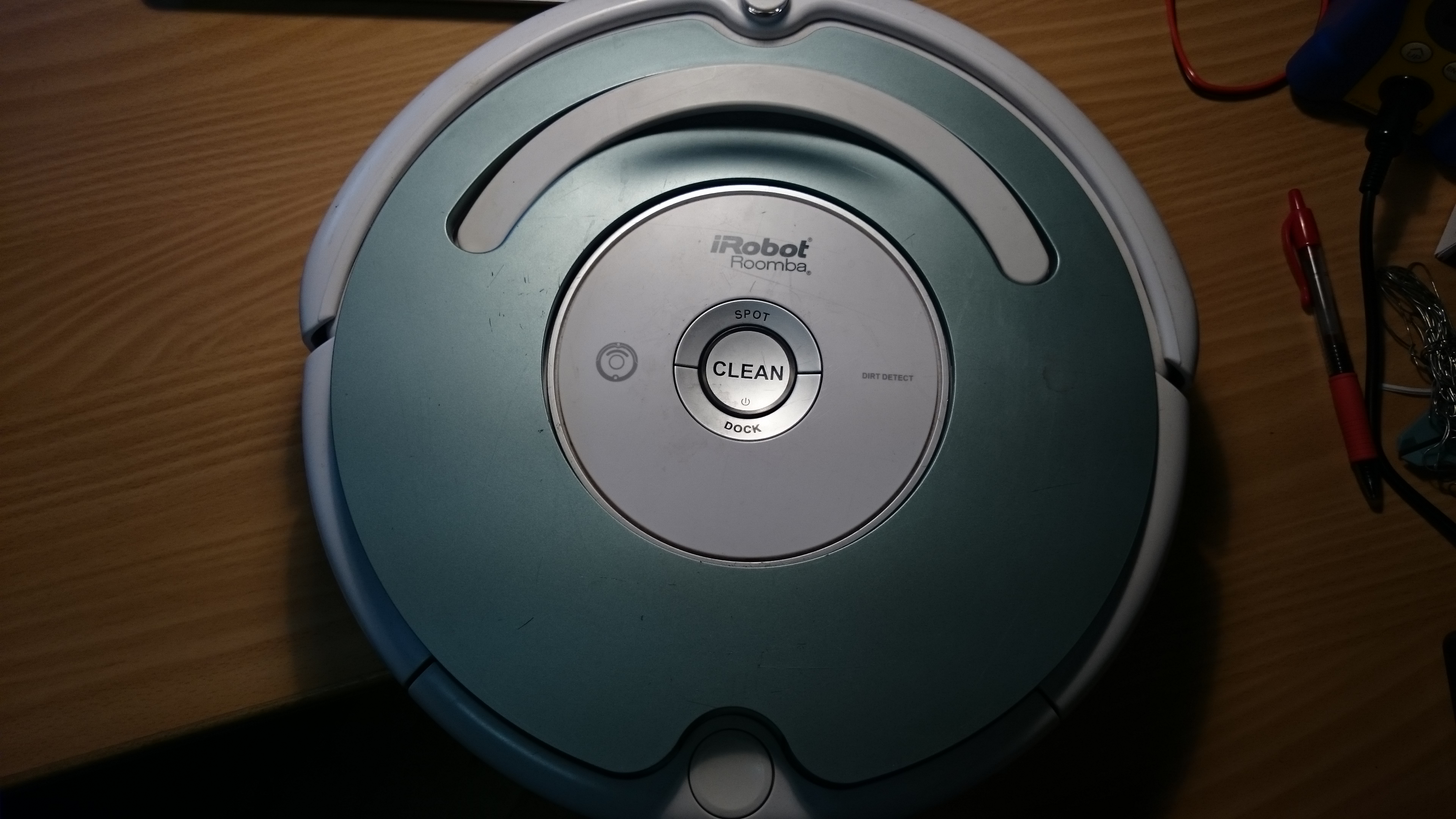
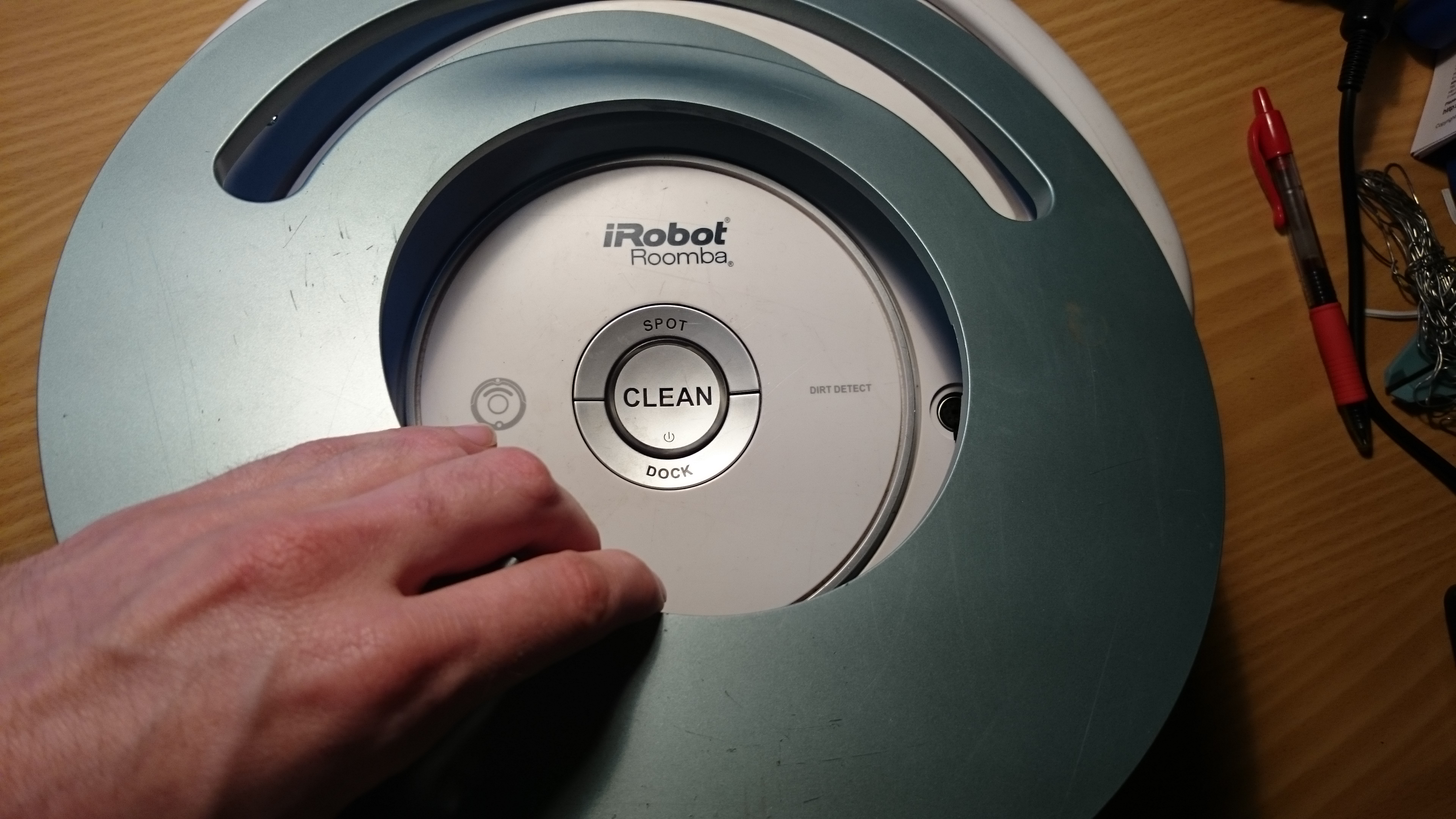
I have a iRobot Roomba 500-series vacuum cleaner robot, but without any remote, or command center or anything; alas, I have to push a button everytime I want the cleaning revolution to start 🙁
But no more! It turns out the Roomba can be programmed, quite easily, to schedule automatically, and all you need is:
- 1 Arduino
- 2 wires
The Roomba actually supports a serial protocol, the iRobot Roomba 500 Open Interface Specification, that allows remote control, driving, sensoring, and scheduling.
Finding the serial port
Remove the plastic cover. It is easiest to remove the vacuum bin, and carefully pry it off with a screwdriver.

There should be a 7-pin plug, on the right side. It has the following pinout:
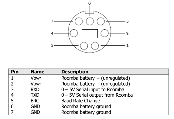
Roomba serial pinout
Program the Arduino
Use this sketch (download: roombaschedule.ino):
/*

Set a schedule on an iRobot Roomba 500 series, using just an Arduino.

Mads Chr. Olesen, 2015.

*/
const byte currentDay = 3;
// 0: Sunday, 1: Monday, 2: Tuesday, 3: Wednesday, 4: Thursday, 5: Friday, 6: Saturday
const byte currentHour = 2;
const byte currentMinute = 58;
// Schedule
const byte SUNDAY = 0x01, MONDAY = 0x02, TUESDAY = 0x04, WEDNESDAY = 0x08, THURSDAY = 0x10, FRIDAY = 0x20, SATURDAY = 0x40;
const byte daystorun = SUNDAY | MONDAY | WEDNESDAY | FRIDAY;
const byte times[14] = {
3, 0, // Sunday time
3, 0, // Monday time
3, 0, // Tuesday time
3, 0, // Wednesday time
3, 0, // Thursday time
3, 0, // Friday time
3, 0, // Saturday time
};
const int ledPin = 13;
void setup() {
Serial.begin(115200);
pinMode(ledPin, OUTPUT);
digitalWrite(ledPin, 0);
Serial.write(128); //Start
delay(1000);
Serial.write(131); //Safe mode, turns off Roomba light
delay(1000);
Serial.write(128); //Start, back to passive mode
delay(500);
//Set day time
Serial.write(168);
Serial.write(currentDay);
Serial.write(currentHour);
Serial.write(currentMinute);
delay(500);
//Set schedule
Serial.write(167);
Serial.write(daystorun);
for (int i = 0; i < 14; i++) {
Serial.write(times[i]);
}
}
void loop() {
digitalWrite(ledPin, 1);
delay(1000);
digitalWrite(ledPin, 0);
delay(1000);
}
You need to modify the variables at the top: set currentDay, currentHour, currentMinute according to the present time.
The pre-programmed schedule is to clean at 03:00 on Sunday, Monday, Wednesday and Friday. You can change this if you wish, by altering the daystorun and times variables.
If you don’t modify the schedule, the Roomba should start automatically after 2 minutes.
Put it all together
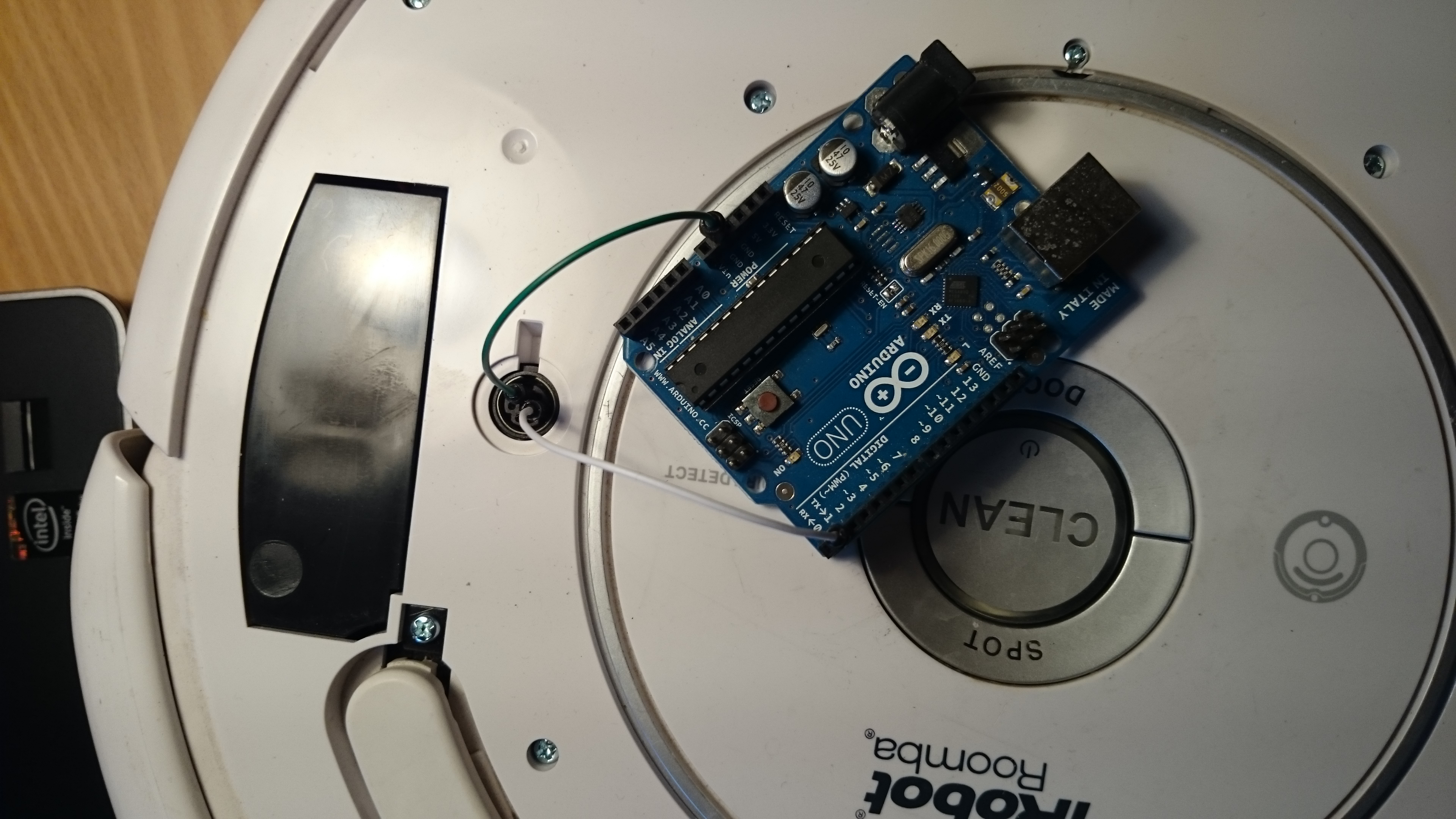
You should now have a partially undressed Roomba, and a programmed Arduino. Now it is time to connect them. With both unpowered, connect the following:
- Arduino GND to Roomba ground (pin 6)
- Arduino TX (pin 1 on e.g. Uno) to Roomba RX (pin 3)
It should look like this:
Now, the moment of truth. Press the “CLEAN” button on the Roomba, the light should go on. Plug in the USB for the Arduino. The Roomba light should turn off briefly, and after a few seconds the Arduino should blink it’s LED. The schedule is now programmed, all done!